


SECTION 1.4
TESTING, CLEANING AND DRYING
PART 1
GENERAL INFORMATION
2. Before reading a DC voltage, always set the meter to a
higher voltage scale than the anticipated reading. if in
doubt, start at the highest scale and adjust the scale
downward until correct readings are obtained.
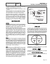
3. The design of some meters is based on the "current flow"
theory while others are based on the "electron flow" theory.
a. The "current flow" theory assumes that
direct current flows from the positive (+) to
the negative (-).
b. The "electron flow" theory assumes that
current flows from negative (-) to positive
(+).
NOTE:
When
testing
generators,
the
"current
flow"
theory
is
applied.
That
is,
current
is
assumed
to
flow
from
positive
(+)
to
negative
(-)).
MEASURING
AC
FREQUENCY
The generator AC output frequency is proportional to
rotor speed. Generators equipped with a 2-pole rotor
must operate at 3600 rpm to supply a frequency of 60
Hertz. Units with 4-pole rotor must run at 1800 rpm to
deliver 60 Hertz.
Correct engine and rotor speed is maintained by an
engine speed governor. For models rated 60 Hertz,
the governor is generally set to maintain a no-load
frequency of about 62 Hertz with a corresponding
output voltage of about 124 volts AC line-to-neutral.
Engine speed and frequency at no-load are set
slightly high to prevent excessive rpm and frequency
droop under heavy electrical loading.
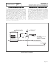
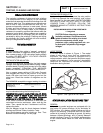
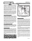
MEASURING
CURRENT
To read the current flow, in AMPERES, a clamp-on
ammeter may be used. This type of meter indicates
current flow through a conductor by measuring the
strength of the magnetic field around that conductor.
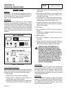
The meter consists essentially of a current
transformer with a split core and a rectifier type
instrument connected to the secondary. The primary
of the current transformer is the conductor through
which the current to be measured flows. The split
core allows the Instrument to be clamped around the
conductor without disconnecting it.
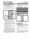
Current flowing through a conductor may be
measured safely and easily. A line-splitter can be
used to measure current in a cord without separating
the conductors.
Figure 2. Clamp-On Ammeter
Figure 3. A Line-Splitter
NOTE:
If
the
physical
size
of
the
conductor
or
ammeter
capacity
does
not
permit
all
lines
to
be
measured
simultaneously,
measure
current
flow
in
each
individual
line.
Then,
add
the
Individual
readings.
MEASURING
RESISTANCE
The volt-ohm-milliammeter may be used to measure
the resistance in a circuit. Resistance values can be
very valuable when testing coils or windings, such as
the stator and rotor windings.
When testing stator windings, keep in mind that the
resistance of these windings is very low. Some
meters are not capable of reading such a low
resistance and will simply read CONTINUITY.
Page 1.4-2