


SECTION 4.4
DIAGNOSTIC TESTS
DC CONTROL
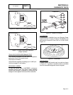
12.Now repeat Step 11 with the negative meter test lead
connected to Connector “C” (Figure 26).
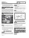
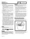
13.Now check the flywheel magnet by holding a
screwdriver at the extreme end of its handle and with its
point down. When the tip of the screwdriver is moved to
within 3/4 inch (19mm) of the magnet, the blade should
be pulled in against the magnet.
14.Now check the flywheel key. The flywheel’s taper is
locked on the crankshaft taper by the torque of the
flywheel nut. A keyway is provided for alignment only
and theoretically carries no load.
Note:
If
the
flywheel
key
becomes
sheared
or
even
partially
sheared,
ignition
timing
can
change.
Incorrect
timing
can
result
in
hard
starting
or
failure
to
start.
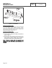
15.As stated earlier, the armature air gap is fixed for single
cylinder engine models and is not adjustable. Visually
inspect the armature air gap and hold down bolts.
16.Disconnect the shutdown ground wire from the armature
and retest for spark, Test 55.
17.Perform Steps 13 and 14.
RESULTS:
If sparking still does not occur after adjusting the
armature air gap, testing the ground wires and
performing the basic flywheel test, replace the ignition
magneto(s).
TEST
60-
CHECK
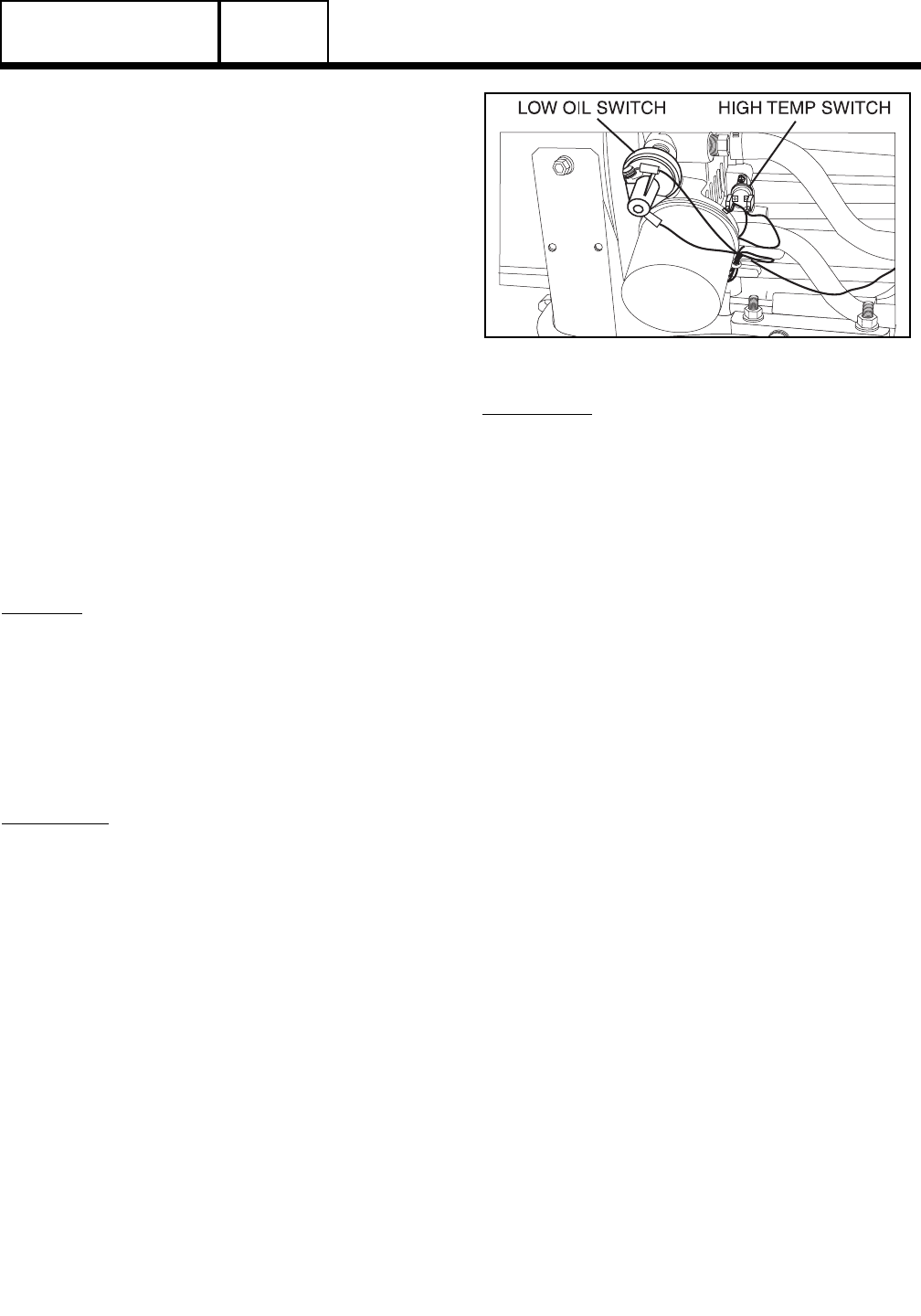
OIL
PRESSURE
SWITCH
AND
WIRE
86
DISCUSSION:
If the oil pressure switch contacts have failed in their
closed position, the engine will probably crank and
start. However, shutdown will then occur within about
5 (five) seconds. If the engine cranks and starts, then
shuts down almost immediately with a LOP fault light,
the cause may be one or more of the following:
❏Low engine oil level.
❏Low oil pressure.
❏A defective oil pressure switch.
If the oil pressure switch contacts have failed open or
Wire 86 does not have continuity to ground at
starting, the engine will not crank. If the engine does
not crank, the cause may be one of the following:
❏A defective oil pressure switch stuck open.
❏An open Wire 86 to Circuit Board.
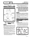
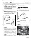
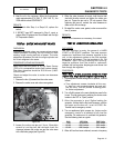
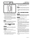
Figure 27. Oil Pressure Switch
PROCEDURE:
Note:
For
Problem
9
Flow
Chart,
perform
Steps
3a,
4
and
5
only.
For
Problem
12
Flow
Chart
perform
all
steps.
1. Check engine crankcase oil level.
a.Check engine oil level.
b.If necessary, add the recommended oil to the
dipstick FULL mark. DO NOT OVERFILL
ABOVE THE FULL MARK.
2. With oil level correct, try starting the engine.
a.If engine still cranks and starts, but then shuts
down, go to Step 3.
b.If engine does not crank go to Step 6.
c. If engine cranks and starts normally, discontinue
tests.
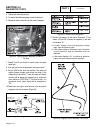
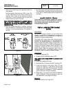
3. Do the following:
a.Disconnect Wire 86 and Wire 0 from the oil
pressure switch terminals. Remove the switch
and install an oil pressure gauge in its place.
b.Connect Wire 86 to Wire 0 for starting purposes
only. After engine starts, remove Wire 86 from
Wire 0.
c. Start the engine while observing the oil pressure
reading on gauge.
d.Note the oil pressure.
(1) Normal oil pressure is approximately 35-40
psi with engine running. If normal oil
pressure is indicated, go to Step 4 of this
test.
(2) If oil pressure is below about 4.5 psi, shut
engine down immediately. A problem exists
in the engine lubrication system.
Note:
The
oil
pressure
switch
is
rated
at
10
psi
for
v-
twin
engines,
and
8
psi
for
single
cylinder
engines.
4. Remove the oil pressure gauge and reinstall the oil
pressure switch. Do NOT connect Wire 86 or Wire 0 to
PART 4
Page 4.4-15