


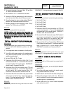
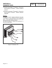
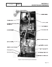
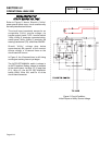
The circuit board mounts a crank relay (K1) and a run
relay (K2, see Figure 4). Crank relay (K1) is
energized by circuit board action during both manual
and automatic startup to crank the engine. Cranking
is accomplished in crank-rest cycles, with the first
cycle being 15 seconds on and 15 seconds off. After
the first crank-rest cycle, the remaining cycles will be
in equal 7-9 second durations. This cyclic cranking
action continues until either (a) the engine starts, or
(b) approximately 90 seconds of the crank-rest cycles
have elapsed.
The run relay is energized by circuit board action at
the same time as the crank relay, to energize and
open a fuel solenoid valve.
DANGER: THE GENERATOR ENGINE WILL
CRANK AND START WHEN THE 7-DAY
EXERCISER SWITCH IS ACTUATED. THE
UNIT WILL ALSO CRANK AND START
EVERY 7 DAYS THEREAFTER, ON THE
DAY AND AT THE TIME OF DAY THE
SWITCH WAS ACTUATED.
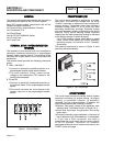
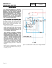
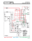
AUTO-OOFF-MMANUAL
SWITCH
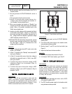
This 3-position switch permits the operator to (a)
select fully automatic operation, (b) start the
generator manually, or (c) stop the engine and
prevent automatic startup. Switch terminals are
shown pictorially and schematically in Figure 5,
below.
Figure 4. The AUTO-OFF-MANUAL Switch
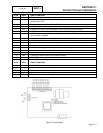
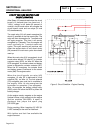
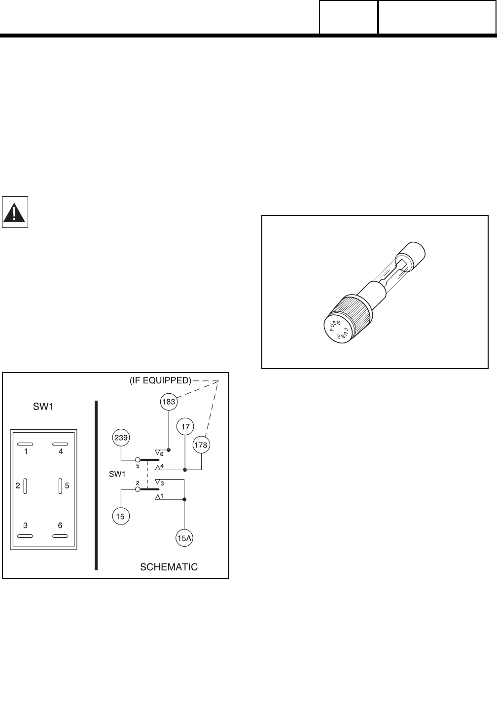
15
AMP
FUSE
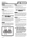
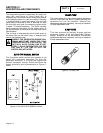
This fuse protects the circuit board against excessive
current. If the fuse has blown, engine cranking and
operation will not be possible. Should fuse
replacement become necessary, use only an identical
15-amp replacement fuse.
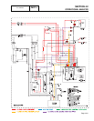
5
AMP
FUSE
This fuse protects the battery charger against
excessive current. If the fuse has blown, battery
charge operation will not be possible. Should fuse
replacement become necessary, use only an identical
5-amp replacement fuse.
Figure 5. 15 Amp Fuse
SECTION 4.1
DESCRIPTION AND COMPONENTS
PART 4
Page 4.1-3
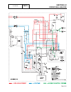
DC CONTROL