


SECTION 3.4
DIAGNOSTIC TESTS
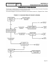
PROCEDURE:
1. Make sure that all main line circuit breakers in the utility
line to the transfer switch are “On” or “Closed.”
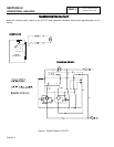
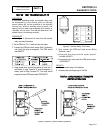
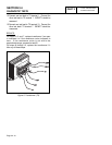
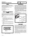
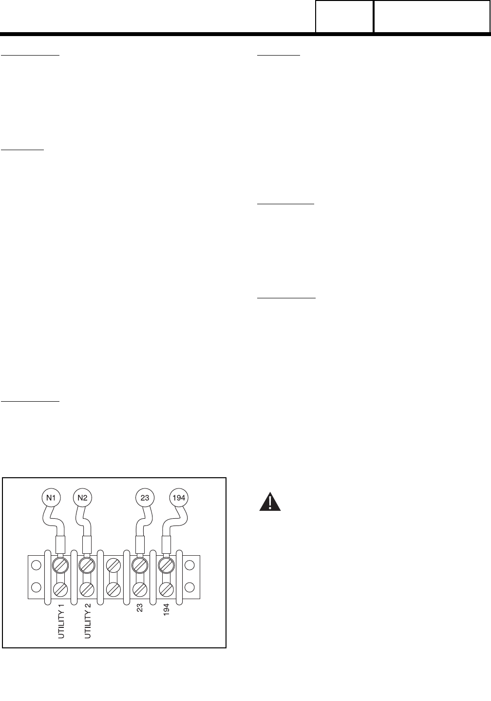
2. Test for utility source line-to-line voltage across terminal
lugs N1 and N2 (see Figure 1). Normal utility source
voltage should be indicated.
RESULTS:
1. If low or no voltage is indicated, find the cause of the
problem and correct.
2. If normal utility source voltage is indicated, go on to
Test 28.
3. For Problem 14 ONLY, if voltage is good, repair or
replace Wire N1A/N2A between Transfer Switch Lugs
N1/N2 and Fuse Holder connections.
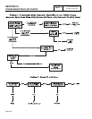
TEST
28
-
CHECK
VOLTAGE
AT
UTILITY
1
AND
UTILITY
2
TERMINALS
The UTILITY 1 and UTILITY 2 terminals in the transfer
switch deliver utility voltage sensing to a circuit board.
If voltage at the terminals is zero or low, standby
generator startup and transfer to the Standby source
will occur automatically as controlled by the circuit
board. A zero or low voltage at these terminals will also
prevent retransfer back to the Utility source.
PROCEDURE:
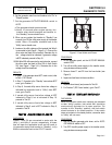
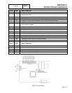
With utility source voltage available to terminal lugs
N1 and N2, use an AC voltmeter or a VOM to test for
utility source line-to-line voltage across terminal block
Utility 1 and Utility 2 terminals. Normal line-to-line
utility source voltage should be indicated.
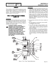
Figure 4. Transfer Switch Terminal Block
RESULTS:
1. If voltage reading across the "Utility I" and "Utility 2"
terminals is zero, go to Test 30.
2. If voltage reading is good, go to Test 29.
3. For Problem 14 ONLY; if voltage is good, repair N1/N2
open wiring between Transfer Switch and Generator.
TEST
29-
CHECK
VOLTAGE
AT
UTILITY
CLOSING
COIL
C1
DISCUSSION:
Utility source voltage is required to energize utility
closing coil C1 and effect retransfer back to the
"Utility" source. This voltage is delivered to the utility
closing coil via Wires N1A and N2A, the transfer
relay’s normally-closed contacts (relay de-energized),
Wire 126, Limit Switch XA1, and a bridge rectifier.
PROCEDURE:
1. On the generator control panel, set the AUTO-OFF-
MANUAL switch to OFF.
2. Turn OFF the utility power supply to the transfer switch,
using whatever means provided (such as a utility source
main line circuit breaker).
3. Set the generator main line circuit breaker to its OFF or
"Open" position.
4. Check the position of the transfer mechanism main
contacts. The moveable load contacts must be
connected to the stationary utility contacts. If necessary,
manually actuate the main contacts to their "Utility
source side (load connected to the "Utility' source).
DANGER: BE CAREFUL! HIGH AND
DANGEROUS VOLTAGES ARE PRESENT AT
TERMINAL LUGS WHEN THE GENERATOR IS
RUNNING. AVOID CONTACT WITH HIGH
VOLTAGE TERMINALS OR DANGEROUS AND
POSSIBLY LETHAL ELECTRICAL SHOCK MAY
RESULT. DO NOT PERFORM THIS VOLTAGE
TEST WHILE STANDING ON WET OR DAMP
GROUND, WHILE BAREFOOT, OR WHILE
HANDS OR FEET ARE WET.
5. Disconnect Wire N2A from the utility closing coil (C1).
Connect one meter test Lead to Wire N2A. Use a suitable
and safe connection to this wire, such as an alligator clip
that attaches to the meter test probe. Isolate this wire and
test probe from any other potential source or ground.
PART 3
V-TYPE PREPACKAGED
TRANSFER SWITCHES
Page 3.4-6