


SECTION 4.2
OPERATIONAL ANALYSIS
PART 4
DC CONTROL
Page 4.2-9
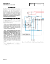
INITIAL
TRANSFER
TO
THE
"STANDBY"
SOURCE
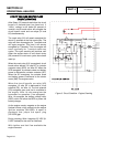
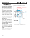
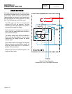
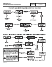
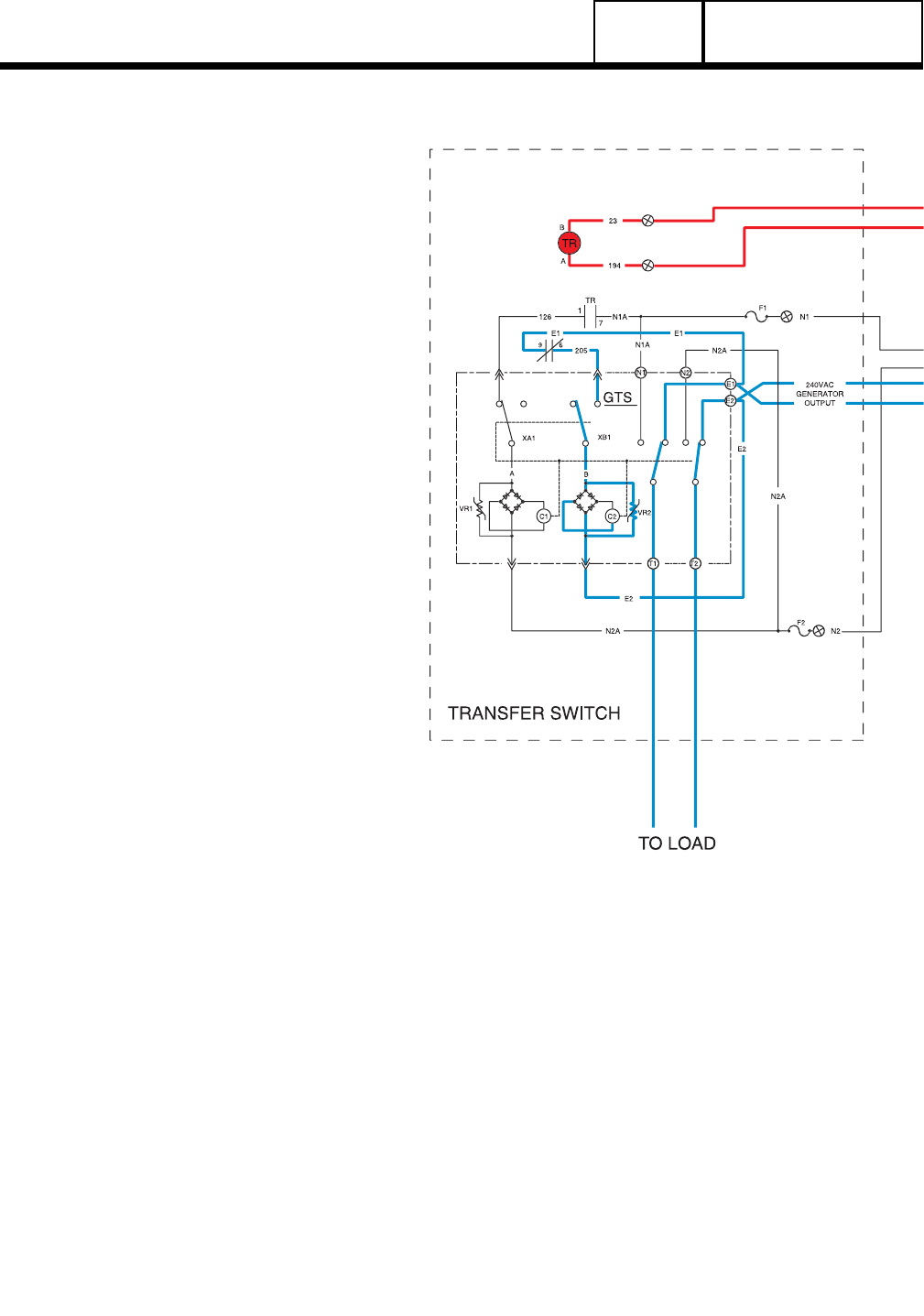
The generator is running, the circuit board’s
"engine warm-up timer" is timing, and generator
AC output is available to transfer switch terminal
lugs E1 and E2 and to the open contacts on the
transfer relay. Initial transfer to the "Standby"
power supply may be briefly described as
follows:
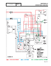
The circuit board delivers a 12 volts DC
output to the transfer relay (TR) actuating coil,
via Wire 194, and terminal A of the transfer
relay (TR) in the transfer switch. This 12 volts
DC circuit is completed back to the board, via
transfer relay terminal B, and Wire 23.
However, circuit board action holds the Wire
23 circuit open to ground and the transfer
relay (TR) is de-energized.
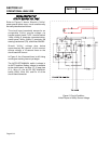
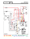
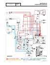
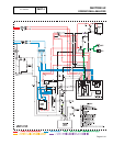
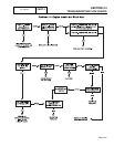
When the circuit board’s "engine warm-up
timer" times out, circuit board action
completes the Wire 23 circuit to ground. The
transfer relay then energizes and its normally
open contacts close.
"Standby" power is now delivered to the
standby closing coil (C2), via Wires E1 /E2,
the normally open transfer relay contacts,
Wire 205, limit switch XB1, Wire B, and a
bridge rectifier. The standby closing coil
energizes and the main current carrying
contacts of the transfer switch are actuated to
their ’Standby" source side.
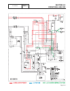
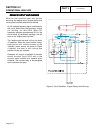
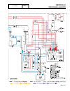
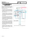
As the main contacts move to their "Standby"
source side, a mechanical interlock actuates
limit switch XB1 to its open position and limit
switch XA1 to its "Utility" side position. When
XB1 opens, standby closing coil C2 3 de-
energizes.
"Standby" power is delivered to the "Load"
terminals (T1/T2) of the transfer switch.
Figure 5. Circuit Condition - Initial Transfer to Standby