


SECTION 1.4
TESTING, CLEANING AND DRYING
PART 1
GENERAL INFORMATION
5. Insert a large paper clip into Pin Location No. 1 (Wire
77). Connect the red tester probe to the paper clip.
Connect the black tester probe to Stator Lead 33. Refer
to Steps 5a through 5c of “TESTING ALL STATOR
WINDINGS TO GROUND” on the previous page.
6. Repeat Step 5 at Pin Location 3 (Wire 66A) and Stator
Lead 33.
7. Repeat Step 5 at Pin Location 7 (Wire 6) and Stator
Lead 33.
For the following steps (8 through 10) an additional
large paper clip (or similar item) will be needed:
8. Insert a large paper clip into Pin Location 1 (Wire 77).
Connect the red tester probe to the paper clip. Insert the
additional large paper clip into Pin Location 3 (Wire
66A). Connect the black tester probe to this paper clip.
Refer to Steps 5a through 5c of “TESTING ALL
STATOR WINDINGS TO GROUND” on the previous
page.
9. Insert a large paper clip into Pin Location 1 (Wire 77).
Connect the red tester probe to the paper clip. Insert the
additional large paper clip into Pin Location 7 (Wire 6).
Connect the black tester probe to this paper clip. Refer
to Steps 5a through 5c of “TESTING ALL STATOR
WINDINGS TO GROUND” on the previous page.
10.Insert a large paper clip into Pin Location 3 (Wire 66A).
Connect the red tester probe to the paper clip. Insert the
additional large paper clip into Pin Location 7 (Wire 6).
Connect the black tester probe to this paper clip. Refer
to Steps 5a through 5c of “TESTING ALL STATOR
WINDINGS TO GROUND” on the previous page.
ROTOR
INSULATION
RESISTANCE
TEST
Before attempting to test rotor insulation, the brush
holder must be completely removed. The rotor must
be completely isolated from other components before
starting the test. Attach all leads of all stator windings
to ground.
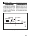
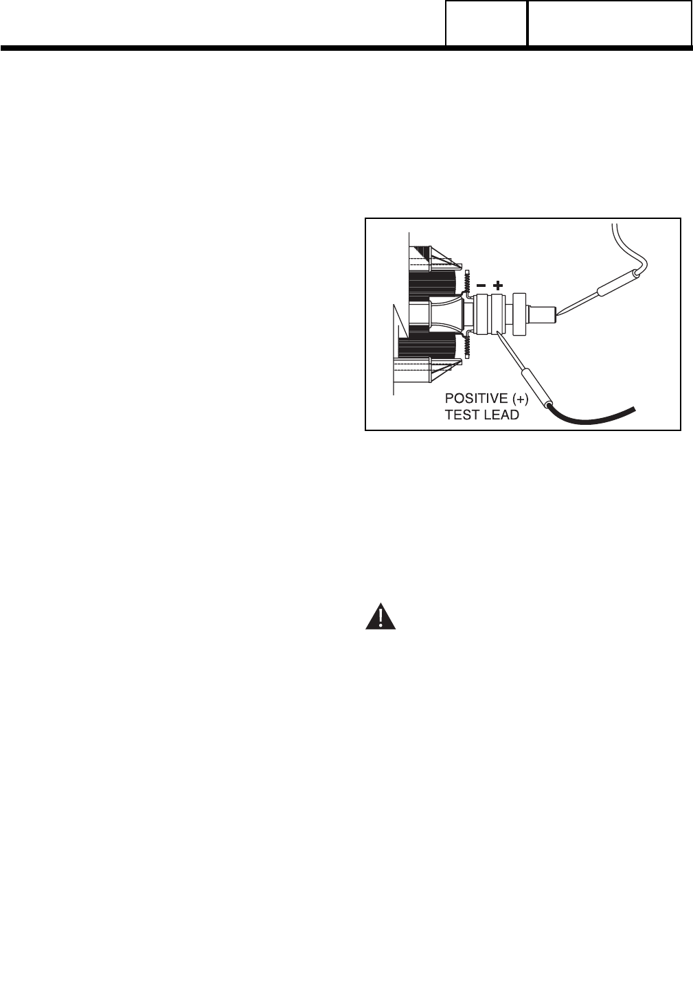
1. Connect the red tester lead to the positive (+) slip ring
(nearest the rotor bearing).
2. Connect the black tester probe to a clean frame ground,
such as a clean metal part of the rotor shaft.
3. Turn the tester switch OFF.
4. Plug the tester into a 120 volts AC wall socket and set
the voltage switch to "1500 volts".
5. Turn the tester switch "On" and make sure the pilot light
has turned on.
6. Observe the breakdown lamp, then turn the tester
switch OFF. DO NOT APPLY VOLTAGE LONGER
THAN ONE (1) SECOND.
If the breakdown lamp came on during the one (1)
second test, cleaning and drying of the rotor may be
necessary. After cleaning and drying, repeat the
insulation breakdown test. If breakdown lamp comes
on during the second test, replace the rotor assembly.
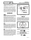
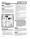
Figure 4. Testing Rotor Insulation
CLEANING
THE
GENERATOR
Caked or greasy dirt may be loosened with a soft
brush or a damp cloth. A vacuum system may be
used to clean up loosened dirt. Dust and dirt may also
be removed using dry, low-pressure air (25 psi
maximum).
CAUTION: Do not use sprayed water to clean
the generator. Some of the water will be
retained on generator windings and terminals,
and may cause very serious problems.
DRYING
THE
GENERATOR
To dry a generator, proceed as follows:
1. Open the generator main circuit breaker. NO
ELECTRICAL LOADS MUST BE APPLIED TO THE
GENERATOR WHILE DRYING.
2. Disconnect all Wires 4 from the voltage regulator.
3. Provide an external source to blow warm, dry air
through the generator interior (around the rotor and
stator windings. DO NOT EXCEED 185° F. (85° C.).
4. Start the generator and let it run for 2 or 3 hours.
5. Shut the generator down and repeat the stator and rotor
insulation resistance tests.
Page 1.4-6