


SECTION 4.4
DIAGNOSTIC TESTS
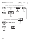
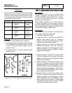
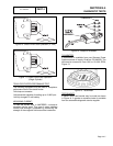
7. Connect the positive (+) test lead to the AUTO-OFF-
MANUAL switch Terminal 4, Wire 17/178. Connect the
negative (-) test lead to a clean frame ground. Battery
voltage should be measured.
8. Connect the positive (+) test lead to Pin location 11, wire
17 at the J1 connector on the circuit board. Connect the
negative (-) test lead to a clean frame ground. Battery
voltage should be measured.
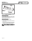
9. Set a VOM to measure resistance "R x 1" scale. Connect
one meter test lead to a clean frame ground. Connect the
other test lead to Pin location 13, Wire 0 at the J1 connector
on the circuit board. CONTINUITY should be measured.
RESULTS:
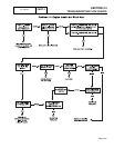
1. No battery voltage in Step 2. Go to test 45 or
repair/replace Wire 15 from F1 to SW1.
2. No battery voltage in Step 3. Go to Test 43 or repair or
replace Wire 15A from Terminal 1 to Terminal 3 of SW1.
3. No battery voltage in Step 4. Verify Step 2 and repair or
replace wire 15 from SW1 to J1 connector.
4. No battery voltage in Step 5. Go to Test 43 or repair or
replace Wire 15A from SW1 to J1 connector.
5. If battery voltage is available in Step 8 but NOT in Step
7, repair or replace Wire 17 from SW1 to J1 connector.
6. If battery voltage is available in Step 7 but NOT in Step
6, go to Test 43.
7. If CONTINUITY is NOT measured in Step 9, repair or
replace Wire 0 between the J1 connector and the 8-tab
ground terminal.
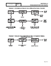
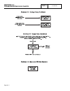
8. If battery voltage is available in Steps 1-5 but NOT in
Step 8 of Problem 2 flow chart, replace or repair the
circuit board.
9. If battery voltage is available in Steps 1-5 for Problem 1
flow chart, replace the circuit board.
Figure 3. Wires 15A
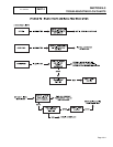
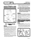
TEST
45-
CHECK
15
AMP
FUSE
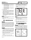
DISCUSSION:
The 15 amp fuse is located on the generator console.
A blown fuse will prevent battery power from reaching
the circuit board, with the same result as setting the
AUTO-OFF-MANUAL switch to OFF.
PROCEDURE:
Remove the 15 amp fuse (F1) by pushing in on fuse
holder cap and turning the cap counterclockwise.
Inspect the fuse visually and with a VOM for an open
condition.
RESULTS:
1. If the fuse if good, go on to Test 46.
2. If the fuse is bad, it should be replaced. Use only an
identical 15 amp replacement fuse.
3. If fuse continues to blow, go to Problem 16.
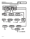
TEST
46-
CHECK
BATTERY
DISCUSSION:
Battery power is used to (a) crank the engine and (b)
to power the circuit board. Low or no battery voltage
can result in failure of the engine to crank, either
manually or during automatic operation.
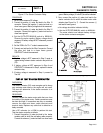
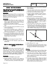
PROCEDURE:
A. Inspect Battery Cables:
1.Visually inspect battery cables and battery
posts.
2.If cable clamps or terminals are corroded, clean
away all corrosion.
3.Install battery cables, making sure all cable
clamps are tight. The red battery cable from the
starter contactor (SC) must be securely
attached to the positive (+) battery post; the
black cable from the frame ground stud must be
tightly attached to the negative (-) battery post.
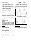
B. Test Battery State of Charge:
1.Use an automotive type battery hydrometer to
test battery state of charge.
2.Follow the hydrometer manufacturer’s
instructions carefully. Read the specific gravity
of the electrolyte fluid in all battery cells.
3.If the hydrometer does not have a "percentage
of charge" scale, compare the reading obtained
to the following:
DC CONTROL
PART 4
Page 4.4-3