


SECTION 1.4
TESTING, CLEANING AND DRYING
PART 1
GENERAL INFORMATION
INSULATION
RESISTANCE
The insulation resistance of stator and rotor windings
is a measurement of the integrity of the insulating
materials that separate the electrical windings from the
generator steel core. This resistance can degrade over
time or due to such contaminants as dust, dirt, oil,
grease and especially moisture. In most cases, failures
of stator and rotor windings is due to a breakdown in
the insulation. And, in many cases, a low insulation
resistance is caused by moisture that collects while the
generator is shut down. When problems are caused by
moisture buildup on the windings, they can usually be
corrected by drying the windings. Cleaning and drying
the windings can usually eliminate dirt and moisture
built up in the generator windings.
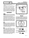
THE
MEGOHMMETER
GENERAL:
A megohmmeter, often called a "megger", consists of
a meter calibrated in megohms and a power supply.
Use a power supply of 500 volts when testing stators
or rotors. DO NOT APPLY VOLTAGE LONGER
THAN ONE (1) SECOND.
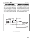
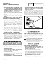
TESTING STATOR INSULATION:
All parts that might be damaged by the high megger
voltages must be disconnected before testing. Isolate
all stator leads (Figure 2) and connect all of the stator
leads together. FOLLOW THE MEGGER
MANUFACTURER’S INSTRUCTIONS CAREFULLY.
Use a megger power setting of 500 volts. Connect
one megger test lead to the junction of all stator
leads, the other test lead to frame ground on the
stator can. Read the number of megohms on the
meter.
The MINIMUM acceptable megger reading for stators
may be calculated using the following formula:
EXAMPLE:
Generator
is
rated
at
120
volts
AC.
Divide
"120"
by
"1000"
to
obtain
"0.12".
Then
add
"1"
to
obtain
"1.12"
megohms.
Minimum
Insulation
resistance
for
a
120
VAC
stator
is
1.12
megohms.
If the stator insulation resistance is less than the
calculated minimum resistance, clean and dry the
stator. Then, repeat the test. If resistance is still low,
replace the stator.
Use the Megger to test for shorts between isolated
windings as outlined "Stator Insulation Tests .
Also test between parallel windings. See "Test
Between Parallel Windings" on this page.
TESTING ROTOR INSULATION:
Apply a voltage of 500 volts across the rotor positive
(+) slip ring (nearest the rotor bearing), and a clean
frame ground (i.e. the rotor shaft). DO NOT EXCEED
500 VOLTS AND DO NOT APPLY VOLTAGE
LONGER THAN 1 SECOND. FOLLOW THE
MEGGER MANUFACTURER’S INSTRUCTIONS
CAREFULLY.
ROTOR MINIMUM INSULATION RESISTANCE:
1.5 megohms
CAUTION: Before attempting to measure
Insulation resistance, first disconnect and
Isolate all leads of the winding to be tested.
Electronic components, diodes, surge
protectors, relays, voltage regulators, etc., can
be destroyed if subjected to high megger
voltages.
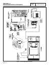
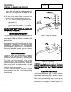
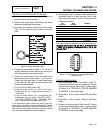
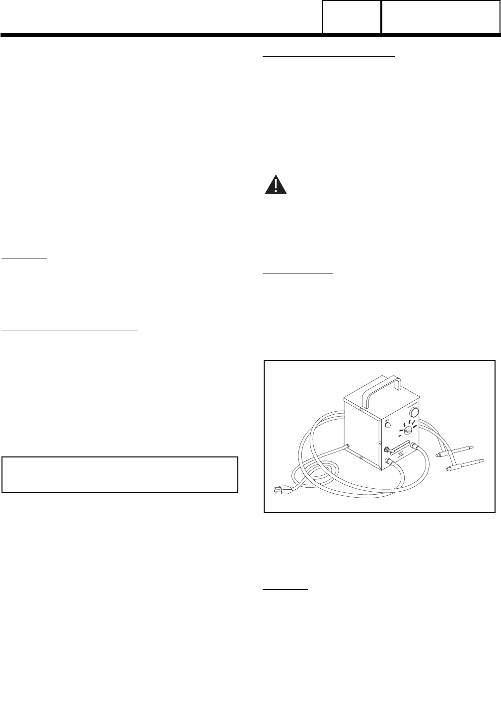
HI-POT TESTER:
A "Hi-Pot" tester is shown in Figure 1. The model
shown is only one of many that are commercially
available. The tester shown is equipped with a
voltage selector switch that permits the power supply
voltage to be selected. It also mounts a breakdown
lamp that will illuminate to indicate an insulation
breakdown during the test.
Figure 1. One Type of Hi-Pot Tester
STATOR
INSULATION
RESISTANCE
TEST
GENERAL:
Units with air-cooled engines are equipped with (a)
dual stator AC power windings, (b) an excitation or
DPE winding, (c) a battery charge winding and (d) an
engine run winding. Insulation tests of the stator
consist of (a) testing all windings to ground, (b) testing
between isolated windings, and (c) testing between
parallel windings. Figure 2 is a pictorial representation
of the various stator leads on units with air-cooled
engine.
Page 1.4-4
MINIMUM INSULATION
GENERATOR RATED VOLTS
RESISTANCE =
__________________________
+1
(in "Megohms")
1000