


SECTION 1.4
TESTING, CLEANING AND DRYING
GENERAL INFORMATION
PART 1
TESTING ALL STATOR WINDINGS TO GROUND:
1. Disconnect stator output leads 11 and 44 from the
generator main line circuit breaker.
2. Remove stator output leads 22 and 33 from the neutral
connection and separate the two leads.
3. Disconnect C2 connector from the side of the control
panel. The C2 connector is the closest to the back
panel.
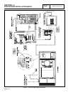
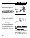
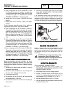
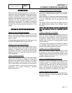
Figure 2. Stator Winding Leads
4. Connect the terminal ends of Wires 11, 22, 33 and 44
together. Make sure the wire ends are not touching any
part of the generator frame or any terminal.
5. Connect the red test probe of the Hi-Pot tester to the
joined terminal ends of stator leads 11, 22, 33 and 44.
Connect the black tester lead to a clean frame ground
on the stator can. With tester leads connected in this
manner, proceed as follows:
a.Turn the Hi-Pot tester switch OFF.
b.Plug the tester cord into a 120 volt AC wall
socket and set its voltage selector switch to
"1500 volts".
c.Turn the tester switch "On" and observe the
breakdown lamp on tester. DO NOT APPLY
VOLTAGE LONGER THAN 1 SECOND. After
one (1) second, turn the tester switch OFF.
If the breakdown lamp comes on during the one-
second test, the stator should be cleaned and dried.
After cleaning and drying, repeat the insulation test. If,
after cleaning and drying, the stator fails the second
test, the stator assembly should be replaced.
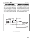
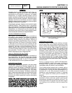
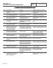
6. Now proceed to the C2 connector. Each winding will be
individually tested for a short to ground. Insert a large
paper clip (or similar item) into the C2 connector at the
following pin locations:
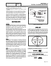
Pin Wire Winding
Location Number
1 77 Battery Charge
2 66 Battery Charge
3 66A Engine Run
4 55 Engine Run
5 22 Sense Lead Power
6 11 Sense Lead Power
7 6 Excitation
8 2 Excitation
Next refer to Steps 5a through 5c of the Hi-Pot procedure.
Example:
Insert
paper
clip
into
Pin
1,
Hi-PPot
from
Pin
1
(Wire
77)
to
ground.
Proceed
to
Pin
2,
Pin
3,
etc.
through
Pin
8.
Figure 3. C2 Connector Pin Location Numbers
(Female Side)
TEST BETWEEN WINDINGS:
1. Insert a large paper clip into Pin Location 1 (Wire 77).
Connect the red tester probe to the paper clip. Connect
the black tester probe to Stator Lead 11. Refer to Steps
5a through 5c of “TESTING ALL STATOR WINDINGS
TO GROUND” on the previous page.
2. Repeat Step 1 at Pin Location 3 (Wire 66A) and Stator
Lead 11.
3. Repeat Step 1 at Pin Location 7 (Wire 6). and Stator
Lead 11.
4. Connect the red test probe to Stator Lead 33. Connect
the black test probe to Stator Lead 11. Refer to Steps
5a through 5c of “TESTING ALL STATOR WINDINGS
TO GROUND” on the previous page.
Page 1.4-5