


SECTION 3.4
DIAGNOSTIC TESTS
PART 3
V-TYPE PREPACKAGED
TRANSFER SWITCHES
DISCUSSION:
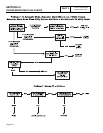
In automatic operating mode, when utility source
voltage drops below a preset level, the engine should
crank and start. On engine startup, an "engine warm-up
timer" on the generator circuit board should start timing.
When that timer has timed out (about 15 seconds), the
transfer relay should energize to deliver utility source
power to the standby closing coil terminals. If normal
utility source voltage is available to the standby closing
coil terminals, but transfer to STANDBY does not occur,
the cause of the failure may be (a) a failed standby
closing coil and/or bridge rectifier, or (b) a seized or
sticking actuating coil or load contact. This test will help
you evaluate whether any sticking or binding is present
in the transfer mechanism.
PROCEDURE:
1. With the generator shut down, set the generator AUTO-
OFF-MANUAL switch to OFF.
2. Set the generator main circuit breaker to OFF or "Open".
3. Turn off the utility power supply to the transfer switch,
using whatever means provided (such as a utility source
main line breaker).
DANGER: DO NOT ATTEMPT MANUAL
TRANSFER SWITCH OPERATION UNTIL ALL
POWER VOLTAGE SUPPLIES TO THE
SWITCH HAVE BEEN POSITIVELY TURNED
OFF. FAILURE TO TURN OFF ALL POWER
VOLTAGE SUPPLIES MAY RESULT IN
EXTREMELY HAZARDOUS AND POSSIBLY
LETHAL ELECTRICAL SHOCK.
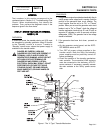
4. In the transfer switch enclosure, locate the manual
transfer handle. Handle is retained in the enclosure with
a wing nut. Remove the wing nut and handle.
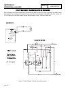
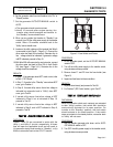
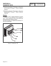
5. See Figure 3. Insert the un-insulated end of the handle
over the transfer switch operating lever.
a.Move the transfer switch operating lever up to
actuate the load contacts to the UTILITY
position, i.e., load connected to the utility source.
b.Actuate the operating lever down to move the
load contacts against the standby contacts, i.e.,
load connected to the STANDBY source.
6. Repeat Step 5 several times. As the transfer switch
operating lever is moved slight force should be needed
until the lever reaches its center position. As the lever
moves past its center position, an over-center spring
should snap the moveable load contacts against the
stationary STANDBY or UTILITY contacts.
7. Finally, actuate the main contacts to their UTILITY power
source side, i.e., load contacts against the UTILITY
contacts (upward movement of the operating lever).
RESULTS:
1. If there is no evidence of binding, sticking, excessive
force required, replace the appropriate closing coil.
2. If evidence of sticking, binding, excessive force required
to move main contacts, find cause of binding or sticking
and repair or replace damaged part(s).
TEST
25-
TEST
LIMIT
SWITCH
XB1
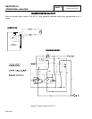
DISCUSSION:
Standby power source voltage must be available to
the standby closing coil in order for a TRANSFER TO
STANDBY action to occur. To deliver that source
voltage to the coil, limit switch XB1 must be closed to
the "Standby" power source side. If the limit switch
did not get actuated or has failed open, the source
voltage will not be available to the closing coil and
transfer to "Standby" will not occur.
PROCEDURE:
With the generator shut down, the generator main
circuit breaker turned OFF, and with the utility power
supply to the transfer switch turned OFF, test limit
switch XB1 as follows:
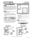
1. To prevent interaction, disconnect Wire 205 and Wire B
from the limit switch terminals.
2. Set a VOM to its "R x 1" scale and zero the meter.
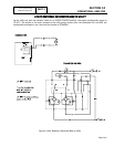
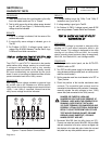
3. See Figure 1. Connect the VOM test probes across
the two outer terminals from which the wires were
disconnected.
4. Manually actuate the main contacts to their "Standby"
position. The meter should read INFINITY.
5. Manually actuate the main contacts to their UTILITY
position. The meter should read CONTINUITY.
6. Repeat Steps 4 and 5 several times and verify the VOM
reading at each switch position.
RESULTS:
1. If Limit Switch XB1 fails the test, remove and replace the
switch or adjust switch until it is actuated properly.
2. If limit switch is good, repair or replace Wire B between
limit switch and Standby Coil (C2).
Page 3.4-4