


SECTION 3.1
DESCRIPTION & COMPONENTS
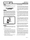
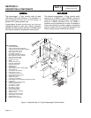
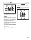
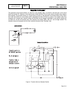
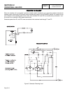
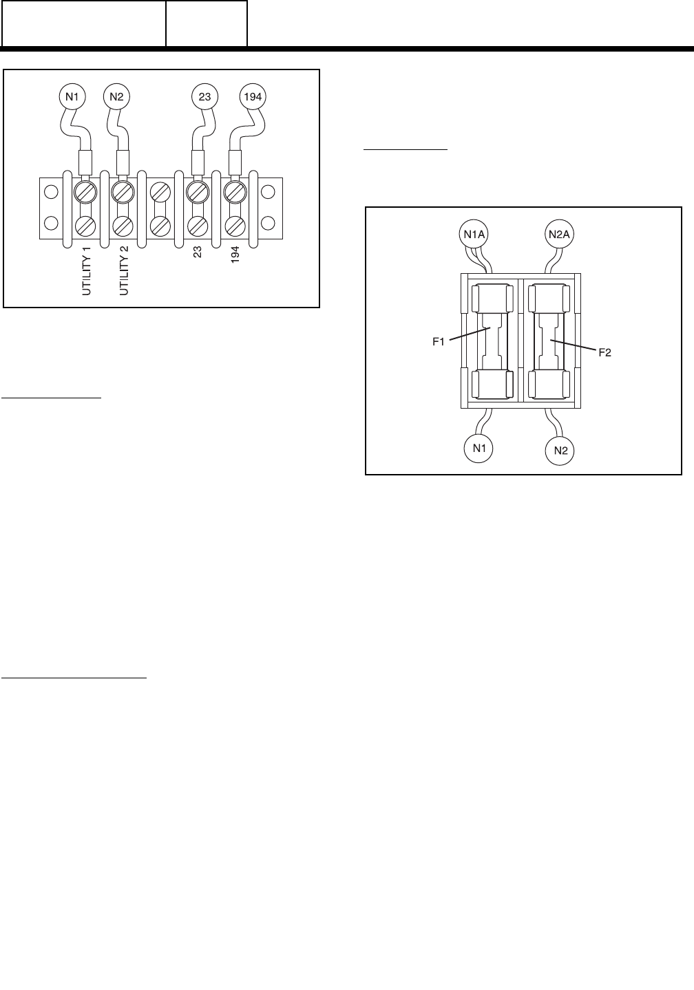
Figure 6. Transfer Switch Terminal Block
Terminals used on the terminal block are identified as
Utility 1 and 2; 23 and 194.
UTILITY 1 AND 2:
Interconnect with identically labeled terminals in the
generator control panel assembly. This is the utility
voltage signal to the circuit board. The signal is
delivered to a step-down transformer in the control
module assembly and the resultant reduced voltage is
then delivered to the circuit board. UTILITY 1 and 2
power is used by the circuit board as follows:
❏If utility source voltage should drop below a preset
level, circuit board action will initiate automatic
cranking and startup, followed by automatic transfer
to the standby source.
❏Utility source voltage is used to operate a battery
trickle charge circuit which helps to maintain battery
state of charge during non-operating periods.
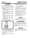
TERMINALS 23 AND 194:
These terminals connect the transfer relay to the
generator circuit board. See "Transfer Relay" on Page
3.1-2.
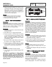
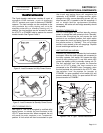
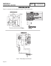
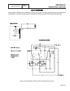
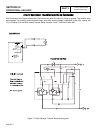
FUSE
HOLDER
The fuse holder holds two (2) fuses, designated as
fuses F1 and F2. Each fuse is rated 5 amperes.
FUSES F1, F2:
These two fuses protect the terminal board UTILITY 1
and 2 circuit against overload.
Figure 7. The Fuse Holder
V-TYPE PREPACKAGED
TRANSFER SWITCHES
PART 3
Page 3-1.4