


SECTION 4.4
DIAGNOSTIC TESTS
TEST
65
-
CHECK
TRANSFORMER
(TX)
VOLTAGE
OUTPUT
DISCUSSION:
The Transformer (TX) is a STEP DOWN type and
has two functions. It supplies approximately 16 VAC to
the control panel circuit board for utility sensing. It also
supplies approximately 16 VAC to the battery charger
for trickle charging. A defective transformer will:
a.not supply AC to the battery charger, and
b.not supply sensing voltage to the circuit board.
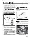
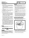
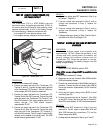
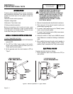
Figure 32. Transformer (TX)
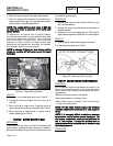
PROCEDURE:
1. Set a VOM to measure AC voltage.
2. Connect one meter test lead to the Transformer (TX)
Terminal 5, Wire N1. Connect the other meter test lead
to the Transformer (TX) Terminal 1, Wire N2. Utility line-
to-line voltage (240 VAC) should be measured.
3. Connect one meter test lead to the Transformer (TX)
Terminal 6 with Wire 225A removed. Connect the other
meter test lead to the Transformer (TX) Terminal 7 with
Wire 224A removed. This output supplies power to the
battery charger. The VOM should measure
approximately 16 VAC.
4. Connect one meter test lead to the Transformer (TX)
Terminal 9 with Wire 224 removed. Connect the other
meter test lead to the Transformer (TX) Terminal 10
with Wire 224 removed. This AC output is used as utility
sensing, and is supplied to the circuit board. The VOM
should measure approximately 16 VAC.
RESULTS:
1. If line-to-line voltage was NOT measured in Step 2, go
to Problem 7, Page 3.3-2.
2. If correct voltage was measured in Step 2, and no
voltage was measured in Step 3, replace the
Transformer.
3. If correct voltage was measured in Step 2, and no
voltage was measured in Step 4, replace the
Transformer.
4. If voltage output was correct for Step 3 and for Step 4,
refer back to the Flow Chart (Page 4.3-5).
TEST
66
-
CHECK
AC
VOLTAGE
AT
BATTERY
CHARGER
DISCUSSION:
The battery charger needs to be supplied with
approximately 16 VAC. When the generator is not
running and utility source power is available, the
battery charger still receives voltage from the
Transformer (TX). When the generator is running,
voltage is supplied to the battery charger from the
battery charge winding.
PROCEDURE:
1. Set the AUTO-OFF-MANUAL switch to OFF.
Note:
Utility
source
voltage
MUST
be
available
to
the
generator.
2. Set a VOM to measure AC voltage.
3. Disconnect the two pin connector (Wire 224B and Wire
225B) at the battery charger.
4. Connect one meter test lead to Wire 224B at the two pin
connector. Connect the other test lead to Wire 225B at
the two pin connector. Approximately 16 VAC should be
measured.
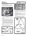
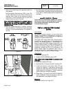
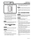
5. Verify that the battery charge relay (BCR) is wired
correctly (Figure 33).
6. Connect one meter test lead to Terminal 1, Wire 224A
on the BCR. Connect the other test lead to Terminal 3,
Wire 225A. Approximately 16 VAC should be measured.
RESULTS:
1. If voltage was NOT measured in Step 6, but was
measured in Test 65, repair or replace Wire 224A and
Wire 225B between the transformer (TX) and the
battery charge relay (BCR).
2. If voltage was not measured in Step 4, go to Test 67.
DC CONTROL
PART 4
Page 4.4-19