


SECTION 3.4
DIAGNOSTIC TESTS
V-TYPE PREPACKAGED
TRANSFER SWITCHES
a. Connect the negative meter lead to the
ground lug. INFINITY should be measured.
b. Connect the negative meter lead to Wire 23
at ICT or terminal strip. INFINITY should be
measured.
c. Connect the negative meter lead to Wire
194 at ICT or terminal strip. INFINITY
should be measured.
d. Connect the negative meter lead to the neutral
connection. INFINITY should be measured.
6. Set your VOM to the 'R x 1" scale. Connect the positive
meter test lead to wire N2.
a. Connect the negative meter lead to the
ground lug. INFINITY should be measured.
b. Connect the negative meter lead to Wire 23
at ICT or terminal strip. INFINITY should be
measured.
c. Connect the negative meter lead to Wire
No. 194 at ICT or terminal strip. INFINITY
should be measured.
d. Connect the negative meter lead to the
neutral connection. INFINITY should be
measured.
7. Disconnect wire N1 and wire N2 from transformer TX.
8. Connect one test lead to wire N1 removed in step 7, and
the other test lead to the ground terminal. INFINITY
should be measured.
9. Connect one test lead to wire N2 removed in step 7, and
the other test lead to the ground terminal. INFINITY
should be measured.
10.If no short is indicated in steps 5 through 9, proceed with
steps 11 through 15. If a short is indicated in steps 5
through 9, repair shorted wiring.
11.Reconnect wires N1 and N2 to the interconnection
terminal or terminal strip.
12.Replace fuses F1 and F2 in the fuse holder.
13.Turn on the utility power supply to the transfer switch
using whatever means is provided.
14.Set VOM to measure AC voltage. Connect one test
lead to wire N1 and the other test lead to wire N2.
Utility line to line voltage should be measured.
15.Turn off the utility power supply to the transfer switch
using whatever means is provided.
RESULTS:
If a short is indicated in steps 5 through 9, repair
wiring and re-test. If utility line to line voltage is
measured in Step 14, proceed to Test 35.
TEST
35
-
CHECK
TRANSFORMER
(TX)
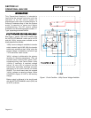
DISCUSSION:
The transformer is a step down type and has two
functions. It supplies approximately 16VAC to the
control board for utility sensing. It also supplies
approximately 16 VAC to the battery charger when
utility is available for trickle charge. A shorted
transformer can result in fuse F1 or F2 blowing.
PROCEDURE:
1. On the generator panel, set the AUTO-OFF-MANUAL
switch to OFF.
2. Turn off the utility power supply to the transfer switch,
using whatever means is provided.
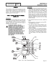
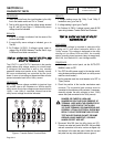
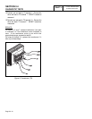
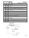
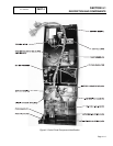
3. See Figure 6. Disconnect Wires N1, N2, 224, 225,
224A, 225A from transformer (TX).
4. Set a VOM to the "R x 1" scale.
5. Connect one test lead to TX terminal 1. Connect the
other test lead to TX terminal 5. Approximately 38.5
ohms should be measured
6. Connect one test lead to TX terminal 10. Connect the
other test lead to TX terminal 9. Approximately 1.5
ohms should be measured.
7. Connect one test lead tot TX terminal 7. Connect the
other test lead to TX terminal 6. Approximately 0.3
ohms should be measured.
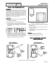
8. Connect one test lead to TX terminal 1. Connect the
other test lead to the transformer case. INFINITY
should be measured.
9. Connect one test lead to TX terminal 7. Connect the
other test lead to the transformer case. INFINITY
should
be measured.
10.Connect one test lead to TX terminal 9. Connect the
other test lead to the transformer case. INFINITY
should be measured.
11.Connect one test lead to TX terminal 1. Connect the
other test lead to TX terminal 10. INFINITY should be
measured.
PART 3
Page 3.4-9