


SECTION 2.4
DIAGNOSTIC TESTS
PART 2
AC GENERATORS
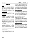
8. Set the AUTO-OFF-MANUAL switch to MANUAL. Once
the engine starts, record the AC voltage.
9. Set the AUTO-OFF-MANUAL switch to OFF.
Reconnect Wire 11 and Wire 22.
10.Set VOM to DC amperage.
11.Remove jumper lead connected to Wire 4 and Wire 15.
12.Connect one meter test lead to battery positive twelve-
volt supply Wire 15, located at the 15A fuse. Connect
the other meter test lead to Wire 4 (still disconnected
from previous tests). Measure and record static rotor
amp draw.
13.Set the AUTO-OFF-MANUAL switch to the MANUAL
position. Once the engine starts, repeat step 12.
Measure and record running rotor amp draw with the
engine running.
14.Set the Auto-Off -Manual switch to OFF. Reconnect
Wire 4 to the voltage regulator.
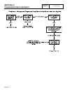
RESULTS:
Refer to Chart on Page 2.4-3: “Results - Fixed Excitation
Test/Rotor Amp Draw Test.”.
TEST
5:
WIRE
CONTINUITY
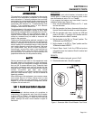
DISCUSSION:
The voltage regulator receives unregulated alternating
current from the stator excitation winding, via Wires 2, 6,
and 162. It also receives voltage sensing from the stator
AC power windings, via Wires 11 and 22. The regulator
rectifies the AC from the excitation winding and based on
the sensing signals, regulates the DC current flow to the
rotor. The rectified and regulated current flow is delivered
to the rotor brushes via Wires 4 (positive) and 0 (negative).
This test will verify the integrity of Wires 0 and 162.
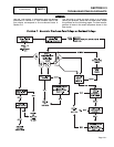
PROCEDURE:
1. Set VOM to its "R x 1" scale.
2. Remove Wire 0 from the voltage regulator, 4th terminal
from the top. Also voltage regulator is labeled (-) next to
terminal.
3. Connect one test lead to Wire 0, connect the other test
lead to a clean frame ground. The meter should read
CONTINUITY.
4. Disconnect Wire 162 from the voltage regulator, 6th
terminal from the top. Disconnect the other end of Wire 162
from the excitation circuit breaker. Connect one test lead to
one end of Wire 162, and the other test lead to the other
end of Wire 162. The meter should read CONTINUITY.
RESULTS:
If CONTINUITY was NOT measured across each wire, repair
or replace the wires as needed.
TEST
6
-
CHECK
FIELD
BOOST
DISCUSSION:
See "Field Boost Circuit" on Page 2.2-1. Field boost current
(from the circuit board) is available to the rotor only while the
engine is cranking. Loss of field boost output to the rotor may
or may not affect power winding AC output voltage. The
following facts apply:
o A small amount of voltage must be induced into the DPE
winding to turn the voltage regulator on.
o If rotor residual magnetism is sufficient to induce a voltage
into the DPE winding that is high enough to turn the voltage
regulator on, regulator excitation current will be supplied
even if field boost has failed. Normal AC output voltage will
then be supplied.
o If rotor residual magnetism has been lost or is not sufficient
to turn the regulator on, and field boost has also been lost,
excitation current will not be supplied to the rotor. Generator
AC output voltage will then drop to zero or nearly zero.
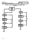
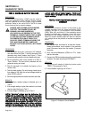
PROCEDURE:
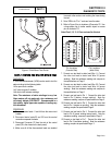
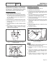
1. Locate Wire 4 that is routed from the circuit board and
connects to the voltage regulator terminal, third from the
top (see Figure 3). Disconnect that wire from the voltage
regulator terminal.
2. Set a VOM to read DC volts. Disconnect Connector C2
from the control panel (C2 is the closest to the back
panel).
3. Connect the positive (+) VOM test probe to the terminal
end of disconnected Wire 4.
4. Connect the common (-) VOM test probe to the
grounding lug.
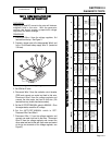
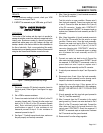
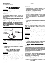
5. Crank the engine while observing the VOM reading. While
the engine is cranking, the VOM should read
approximately 9-10 volts DC. When engine is not
cranking, VOM should indicate "zero" volts (see Figure 4).
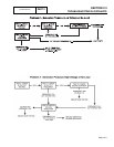
RESULTS:
1. If normal field boost voltage is indicated in Step 5,
replace the voltage regulator.
2. If normal field boost voltage is NOT indicated in Step 5,
check Wire 4 (between regulator and circuit board) for
open or shorted condition. If wire is good, replace the
circuit board.
Page 2.4-4