


SECTION 2.2
OPERATIONAL ANALYSIS
PART 2
AC GENERATORS
OPERATION
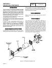
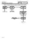
STARTUP:
When the engine is started, residual plus field boost
magnetism from the rotor induces a voltage into (a)
the stator AC power windings, (b) the stator excitation
or DPE windings, (c) the stator battery charge, and (d)
engine run winding. In an "on-speed" condition,
residual plus field boost magnetism are capable of
creating approximately one-half the unit’s rated
voltage.
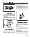
ON-SPEED OPERATION:
As the engine accelerates, the voltage that is induced
into the stator windings increases rapidly, due to the
increasing speed at which the rotor operates.
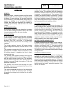
FIELD EXCITATION:
An AC voltage is induced into the stator excitation
(DPE) windings. The DPE winding circuit is completed
to the voltage regulator, via Wire 2, excitation circuit
breaker, Wire 162, and Wire 6. Unregulated
alternating current can flow from the winding to the
regulator.
The voltage regulator "senses" AC power winding
output voltage and frequency via stator Wires 11 and
22.
The regulator changes the AC from the excitation
winding to DC. In addition, based on the Wires 11 and
22 sensing signals, it regulates the flow of direct
current to the rotor.
The rectified and regulated current flow from the
regulator is delivered to the rotor windings, via Wire 4,
and the positive brush and slip ring. This excitation
current flows through the rotor windings and is
directed to ground through the negative (-) slip ring
and brush, and Wire 0.
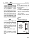
The greater the current flow through the rotor
windings, the more concentrated the lines of flux
around the rotor become.
The more concentrated the lines of flux around the
rotor that cut across the stationary stator windings,
the greater the voltage that is induced into the stator
windings.
Initially, the AC power winding voltage sensed by the
regulator is low. The regulator reacts by increasing
the flow of excitation current to the rotor until voltage
increases to a desired level. The regulator then
maintains the desired voltage. For example, if voltage
exceeds the desired level, the regulator will decrease
the flow of excitation current. Conversely, if voltage
drops below the desired level, the regulator responds
by increasing the flow of excitation current.
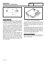
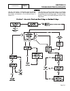
AC POWER WINDING OUTPUT:
A regulated voltage is induced into the stator AC
power windings. When electrical loads are connected
across the AC power windings to complete the circuit,
current can flow in the circuit. The regulated AC
power winding output voltage will be in direct
proportion to the AC frequency. For example, on units
rated 120/240 volts at 60 Hz, the regulator will try to
maintain 240 volts (line-to-line) at 60 Hz. This type of
regulation system provides greatly improved motor
starting capability over other types of systems.
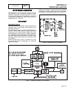
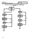
BATTERY CHARGE WINDING OUTPUT:
A voltage is induced into the battery charge windings.
Output from these windings is delivered to a battery
charger, via Wires 66 and 77. The resulting direct
current from the battery charger is delivered to the
unit battery, via Wire 15, a 15 amp fuse, and Wire 13.
This output is used to maintain battery state of charge
during operation.
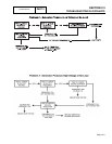
ENGINE RUN WINDING OUTPUT:
A voltage is induced into the engine run winding and
delivered to a solid state circuit board , via Wire 66A.
This output "tells" the circuit board that the engine has
started and what its operating speed is. The circuit
board uses these signals from the engine run winding
to (a) terminate cranking, and (b) turn on various
timing circuits that control automatic operation. See
Part 4, "DC Control".
Page 2.2-2