


SECTION 4.2
OPERATIONAL ANALYSIS
PART 4
DC CONTROL
INITIAL
DROPOUT
OF
UTILITY
SOURCE
VOLTAGE
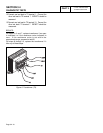
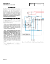
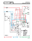
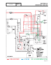
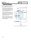
Refer to Figure 2, above. Should a "Utility"
power source failure occur, circuit condition may
be briefly described as follows:
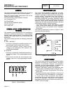
The circuit board constantly senses for an
acceptable "Utility" source voltage, via
transfer switch fuses F1/F2, transfer switch
"Utility 1/Utility 2" terminals, connected wiring,
control panel "Utility 1/Utility 2" terminals, the
sensing transformer (TX), and Wires 224/225.
Should "Utility" voltage drop below
approximately 60 percent of the nominal
source voltage, a 15-second timer on the
circuit board will turn on.
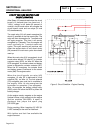
In Figure 2, the 15-second timer is still timing
and engine cranking has not yet begun.
The AUTO-OFF-MANUAL switch is shown in
its AUTO position. Battery voltage is available
to the circuit board, via Wire 13, 15 amp fuse
(F1), Wire 15, the AUTO-OFF-MANUAL
switch (SW1), Wire 15A, and Pin 10 of the
circuit board connector.
Page 4.2-3
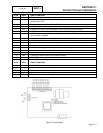
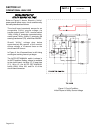
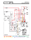
Figure 2. Circuit Condition -
Initial Dropout of Utility Source Voltage