


SECTION 2.4
DIAGNOSTIC TESTS
AC GENERATORS
RESULTS:
1. If the resistance reading is correct, check your VOM
meters fuse and repeat Test 4.
2. If INFINITY is measured on your VOM meter, go to Test 9.
TEST
9
-
CHECK
BRUSHES
AND
SLIP
RINGS
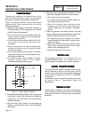
DISCUSSION:
The function of the brushes and slip rings is to provide for
passage of excitation current from stationary components to the
rotating rotor. Brushes are made of a special long lasting
material and seldom wear out or fail. However, slip rings can
develop a tarnish or film that can inhibit or offer a resistance to
the flow of electricity. Such a non-conducting film usually
develops during non-operating periods. Broken or disconnected
wiring can also cause loss of excitation current to the rotor.
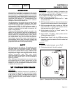
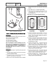
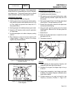
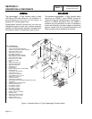
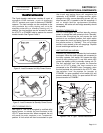
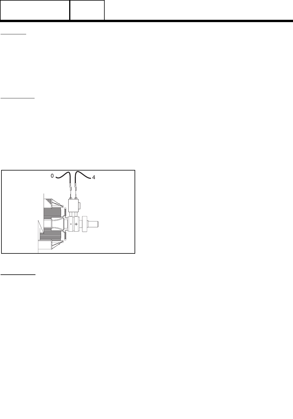
Figure 7. Checking Brushes and Slip Rings
PROCEDURE:
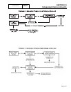
1. Disconnect connector C2 (deutsch connector closest to
the back panel). Refer to figure 5 and figure 6 on page
2.4-5.
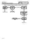
2. Set a VOM to measure resistance.
3. Connect one meter test lead to Pin 9 (Wire 0) of the C2
connector (female side). Connect the other meter test
lead to Pin 10 (Wire 4) of the C2 connector (female
side). Rotor resistance should be measured see
specifications on page 2. If rotor resistance is not
measured proceed to step 4. If rotor resistance is
measured proceed to step 12.
4. See figure 7. Carefully inspect brush wires; make sure
they are properly and securely connected.
5. Wire 0 from the negative (-) brush terminal connects to
Pin 9 of the C2 connector.
Test this wire for an open condition. Remove wire 0
from the brush assembly. Connect one meter test lead
to wire 0. Connect the other test lead to Pin 9 (wire 0)
of the C2 connector ( female side). CONTINUITY
should be measured. If INFINITY is measured repair or
replace wire 0 between the brush assembly and the C2
connector.
6. Wire 4 from the positive (+) brush terminal connects to
Pin 10 of the C2 connector.Test this wire for an open
condition. Remove wire 4 from the brush assembly.
Connect one meter test lead to Wire 4. Connect the
other meter test lead to Pin 10 (wire 0) of the C2
connector (female side). CONTINUITY should be
measured. If INFINITY is measured repair or replace
wire 4 between the brush assembly and the C2
connector.
7. Connect one meter test lead to wire 4 Connect the
other meter test lead to frame ground. INFINITY should
be measured. If CONTINUITY is measured a short to
ground exists on wire 4 repair or replace wire 4
between the brush assembly and the C2 connector.
8. If continuity was measured in steps 5 and 6 proceed to
step 9.
9. Disconnect wires 0 and 4 from the brush assembly.
Remove the brush assembly from the bearing carrier.
Inspect the brushes for excessive wear,damage.
10. Inspect the rotor slip rings. If they appear dull or
tarnished, they may be polished with a fine sandpaper.
DO NOT USE METALLIC GRIT TO POLISH SLIP
RINGS.
11. If brush assembly and slip rings look good proceed to
Test 10 ( Test Rotor assembly)
12. Wire 0 connects from the C2 connector to the control
panel ground lug. Connect one meter test lead to Pin 9
(Wire 0) of the C2 connector (male side). Connect the
other meter test lead to the ground terminal in the
control panel. CONTINUITY should be measured. If
INFINITY is measured repair or replace wire 0 between
the C2 connector and the ground terminal.
13. Remove wire 4 from the voltage regulator.
PART 2
Page 2.4-7