


INSTALLATION LBI-39128
9
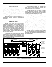
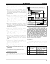
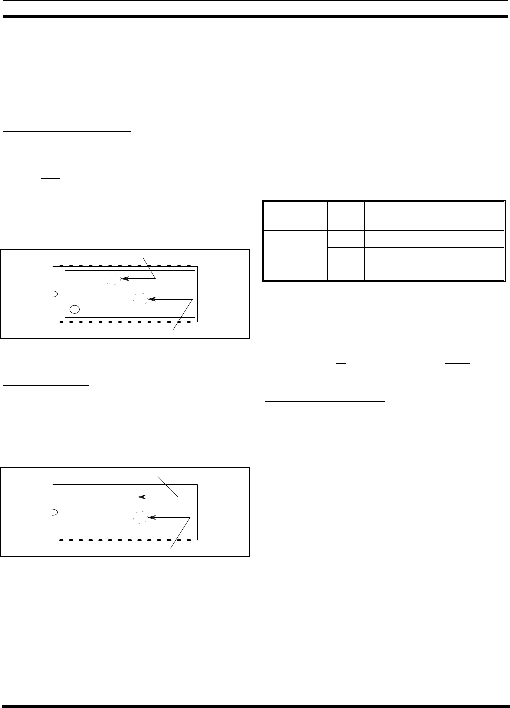
The location of the Application Software and
Personality PROMs on the PROM card is shown in Figure
6. When replacing PROMs, be sure to get each new PROM
in the correct location, and with the notched end as shown.
Be especially careful of location numbers 01 and 02 since
these numbers are used for both sets of PROMs.
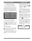
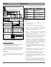
Application Software PROMs
Check the revision number marked on the Application
Software PROMs. Each of the 14 Application Software
PROMs must be marked 344A3265Gx, where x = 6 or
higher. (Application Software with x = 5 or lower will not
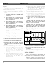
work for the new PMU option.) Figure 7 shows where to
find the software revision number and the PROM location
number on a typical Application Software PROM label.
Replace all 14 Application Software PROMs if required.
344A3265G6
VAX SITE CTRLR
EDACS
1994 BY ERICSSON GE
C
01
PROM Location
Software Revision
Figure 7 - Application Software PROM Label
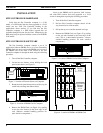
Personality PROMs
Replace the two Personality PROMs, even if a PMU
was previously installed with this Site Controller computer.
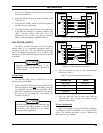
Figure 8 shows a typical Personality PROM label. (See the
Application Notes section if you need to order new
Personality PROMs.)
SER#: 12345678
SITE CONTROLLER
EDACS
PERSONALITY
01
PROM Location
Serial Number
Figure 8 - Personality PROM Label
PMU HARDWARE
There are three procedures for the installation of the
PMU hardware. The procedure you should use will depend
upon whether or not the Site Controller cabinet presently
contains EDACS Interface Panels and/or an old PMU. The
EDACS Interface Panels are located in the back of the
cabinet, near the top. Each panel consists of a 5 1/4 inch X
19 inch frame containing one or more interface modules
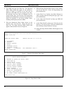
(boards with connectors). Use Table 1 to select the right
PMU hardware installation procedure for your system.
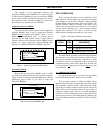
Table 1 - Selection of Installation Procedure
INTERFACE
PANEL
OLD
PMU
HARDWARE INSTALLATION
PROCEDURE
Yes No A. Addition from No PMU
Yes B. Upgrade from Old PMU
No Yes C. Adaptation from Old PMU
The table and the procedures assume that the equipment
that presently exists in the Site Controller cabinet is one of
the previous standard configurations. Regardless of which
procedure is used, it is very important to know exactly what
equipment presently exists, review what has to be done, and
be sure you have all the parts you will need before
you start
the installation.
A. Addition from No PMU
Use this procedure only if your Site Controller cabinet
has EDACS Interface panels, but doesn’t have a PMU.
This procedure consists of adding the PMU, Power
Monitor interface module, cables between the PMU and the
Power Monitor interface module, cable between the PMU
and the Site Controller computer, and DC power wires to the
PMU, all in the Site Controller cabinet. It also consists of
adding the antenna power sensor(s) in the RF Equipment
cabinet(s), and the antenna power sensor cables between the
antenna power sensor(s) in the RF Equipment cabinet(s) and
the Power Monitor interface module in the Site Controller
cabinet.