


LBI-39128 GLOSSARY
Ericsson Inc.
Private Radio Systems
Mountain View Road
Lynchburg, Virginia 24502
1-800-528-7711 (Outside USA, 804-528-7711) Printed in U.S.A.
GLOSSARY
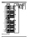
Antenna Mapping.........................................................Antenna Mapping is the process of re-configuring the PMU’s Antenna
Channel parameter through the use of an RS-232 CRT terminal (or PC
with terminal emulation software). This parameter tells the PMU which
antenna is used by each transmitter (actually, which Analog Input # is
connected to that antenna’s power sensor).
EDACS ........................................................................Enhanced D
igital Access Communications System
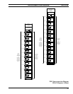
EDACS Interface Panel ...............................................An EDACS Interface Panel is a 19-inch wide panel mounted in the top
rear of each EDACS Repeater and Site Controller cabinet. The panels
are used as the connection point for all cables between adjacent
EDACS Repeater and Site Controller cabinets.
Power Sensor ...............................................................The Power Sensor is the RF power-detecting device used by the PMU
to monitor the power at a specific point in the RF transmit path. The
power sensor may be unidirectional (senses power in one direction) or
bi-directional (senses power in both directions).
Power Sensor Module..................................................The Power Sensor module is the name of the board used in the upper
EDACS Interface Panel of a Site Controller cabinet containing the
PMU option. Its sole function is to provide a connection point between
cables going to the PMU (inside the cabinet) and cables going to the
power sensors (outside the cabinet).
RS232 CRT Terminal ..................................................CRT terminal with RS232 interface that can be used to communicate
with and configure terminal-configurable software. Also includes PC
operating in the terminal mode with terminal emulation software.
SWR.............................................................................The Standing W
ave Ratio is the ratio of the amplitude of a standing
wave at an anti-node to the amplitude at a node.
VDT Interface..............................................................Both VDT Interfaces on the back of the PMU are RS232 ports with
default baud rates of 9600 BPS. The left-hand VDT Interface is used
for the connection to a programming terminal. The right-hand VDT
Interface is used for the connection to the Site Controller computer.