


LBI-39128 FIGURES AND TABLES
4
LIST OF FIGURES AND TABLES
Page
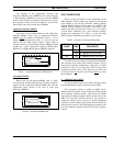
Figure 1 - Location of PMU Components.................................................................................................... 6
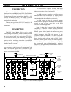
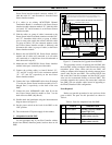
Figure 2 - Card Layout for PDP Upgraded to VAX .................................................................................... 7
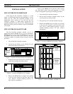
Figure 3 - Location of Fastener Screws on Computer.................................................................................. 8
Figure 4 - Location of PROM Card in Computer ........................................................................................ 8
Figure 5 - Location of PROM Card in Older Computer .............................................................................. 8
Figure 6 - Location of PROMs on PROM Card .......................................................................................... 8
Figure 7 - Application Software PROM Label ............................................................................................ 9
Figure 8 - Personality PROM Label ............................................................................................................ 9
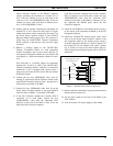
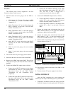
Figure 9 - Antenna Power Sensor Connections............................................................................................ 11
Figure 10 - Connections for Addition from No PMU.................................................................................. 12
Figure 11 - Connections for Upgrade from Old PMU ................................................................................. 13
Figure 12 - Connections for Adaptation from Old PMU ............................................................................. 14
Figure 13 - DB-25 Terminal Connections ................................................................................................... 15
Figure 14 - DB-9 Terminal Connections ..................................................................................................... 15
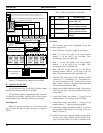
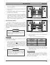
Figure 15 - Operation Select Menu (Main Menu) ....................................................................................... 16
Figure 16 - Setup Selection Menu ............................................................................................................... 16
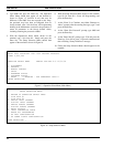
Figure 17 - Site Data #1 Screen................................................................................................................... 17
Figure 18 - Analog Input Channel Screen.................................................................................................... 18
Figure 19 - Analog Input Channel Screen Showing Antenna Channel Parameter ....................................... 19
Figure 20 - Unidirectional Power Sensor Calibration Screw....................................................................... 19
Figure 21 - Bi-directional Power Sensor Calibration Screws ...................................................................... 20
Figure 22 - Analog Pseudo Channel Screen ................................................................................................ 29
Figure 23 - Report Selection Menu.............................................................................................................. 31
Figure 24 - Alarm History Report Screen.................................................................................................... 31
Figure 25 - Channel Monitor Screen............................................................................................................ 31
Figure 26 - Location of PMU Software ....................................................................................................... 32
Figure 27 - Location of DIP Switches ......................................................................................................... 33
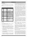
Table 1 - Selection of Installation Procedure............................................................................................... 9
Table 2 - Parts for Addition from No PMU................................................................................................. 10
Table 3 - Parts for Upgrade from Old PMU ................................................................................................ 12
Table 4 - Parts for Adaptation from Old PMU ............................................................................................ 13
Table 5 - Terminal Communications Protocol............................................................................................. 15
Table 6 - Power Sensor Voltage-to-Power Conversion Table ..................................................................... 21
Table 7 - PMU Option Parameters .............................................................................................................. 26
Table 8 - SWR Upper Limit ........................................................................................................................ 30
Table 9 - Channel Numbers for Channel Monitor Screen............................................................................ 32
Table 10 - Troubleshooting Symptoms........................................................................................................ 34