MAINTENANCE LBI-39128
33
want to return the PMU’s parameters to the factory default
values, use the Software Initialization process described in
the Installation section (its much easier).
Use the following procedure to erase all programming.
Note that this will undo all programming by the user
(including antenna mapping during installation).
1. Switch the PMU’s On-Off switch to the off position.
2. Label and disconnect all cables and wires connected to
the PMU.
3. Remove the PMU from the cabinet and remove the top
cover.
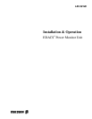
4. Set DIP switch #1 to the on position as shown in Figure
27.
18
ON
OFF
= Moveable Button
Figure 27 - Location of DIP Switches
5. Return the PMU to the cabinet and re-connect just the
DC power wires.
6. Switch the PMU’s On-Off switch to the on position for
a few seconds, and then back to the off position.
7. Disconnect the DC power wires and remove the PMU
from the cabinet.
8. Return DIP switch #1 to the off position. (If you forget
to set DIP switch #1 back to the off position, user
programming is erased each time it is powered on.)
9. Replace the top cover on the PMU, and re-mount the
PMU in the cabinet.
10. Re-connect all wires and cables disconnected in step 2.
11. Switch the PMU’s On-Off switch to the on position.
Don’t forget to redo any necessary programming
(including antenna mapping). See the Programming heading
in the Installation section.
ALARM DELAY ADJUSTMENT
The Alarm Delay parameter determines the delay
between when the PMU first receives information that a
transmitter channel is being keyed and when the PMU starts
reporting an alarm (if there is an alarm) for that transmitter
channel. This delay is necessary to prevent the PMU from
reporting an alarm before the transmitter is actually turned
on or before it has had a chance to reach full power.
This parameter has been given the default value of 3.
However, in some systems it may be necessary to increase
this value to as much as 8. The larger the number , the
longer the delay, and the lower the probability of an alarm
being reported when everything is OK. However, the longer
the delay, the more frequently a call will be too short to be
monitored by the PMU. Therefore, it is desirable to use as
low a value as possible. Never use a value lower than 3.
The value of this parameter may be changed in the
PMU’s Active Configuration through an RS232 CRT
terminal connected to the PMU. See the PMU Programming
heading in the Installation section to set up the terminal and
obtain programming access.
To increase the value of the Alarm Delay parameter, use
the following procedure:
1. With the Operational Select Menu (main menu)
showing on the terminal, type 4 (for item #4 - Setup)
and press the Enter key.
2. With the Setup Selection Menu shown on the terminal,
type 4 (for item #4 - Analog Input Channel) and press
the Enter key.
3. At the “Enter Channel Number” prompt, type the
channel number of the transmitter and press the Enter
key. The Analog Input Channel screen for that
transmitter channel should then appear on the terminal.
4. Type 5 (for item #5 - Alarm Delay) and press the Enter
key.
5. At the “Enter New Data” prompt, type the new value
(never use a value less than 3) and press the Enter key.
The screen should then be updated to show the new
value.
6. Type E (to End programming this channel) and press
the Enter key. The Setup Selection Menu should then
appear on the terminal.
This completes the re-configuration of the Alarm Delay
parameter for the selected transmitter channel number. This
parameter should be re-configured the same for all