


OPERATION LBI-39128
23
transmitters, make all the required power and SWR
calculations, and compare all measurements and calculations
to the applicable high and low alarm limits. Only alarm
conditions that are measured 750 milliseconds or more after
the associated transmitter is keyed are used to send an alarm
to the Site Controller computer. This gives the transmitter
time to reach full power and avoid false alarms.
These messages also tell the PMU when each
transmitter is about to be unkeyed (about to stop
transmitting). This advance warning will prevent the PMU
from making measurements while or after the associated
transmitter is unkeyed, again to avoid false alarms.
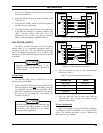
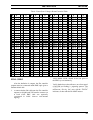
Power Measurements
The PMU makes power measurements by measuring the
dc voltages from the power sensors connected to its Analog
Inputs. Each dc voltage measurement is translated into a
power level by using a table of equivalents that was
empirically derived from the typical characteristic of a 1000
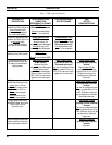
watt power sensor. This table, shown in Table 7, contains
only certain discrete power levels. Therefore, power
measurements made by the PMU can only be one of these
discrete power levels, nothing between.
Any specific power level (P) given in the table
represents a range of dc voltages (V) from the sensor. The
lower limit of this range is the voltage shown in the same
row of the table as the power. The upper limit of this range
is the voltage shown in the next lower row of the table.
Because voltage ranges and a look-up table are used to
determine a power level (as opposed to using an actual
mathematical calculation), a voltage measurement that is
teetering on the dividing line between two voltage ranges
will appear to be jumping as much as 2.5 watts at the 100
watt level (98.8 to 101.3) and give the impression that the
power level is unsteady when it isn’t. If one of these power
levels is within the alarm limits and the other is out, you may
see this as an intermittent alarm.
When the PMU is told by the Site Controller computer
that a specific transmitter is keyed, the PMU measures the
dc voltage from the power sensor installed in that
transmitter’s output circuit, determines the power using the
values shown in Table 7, and compares the power to the
high and low alarm limits for this transmitter. If the power is
within the limits, nothing more happens. If the power is not
within the limits, an alarm for this transmitter is sent to the
Site Controller computer (see the Alarms heading).
When the PMU is told by the Site Controller computer
that a specific transmitter is keyed, the PMU also measures
the forward power dc voltage from the power sensor
installed in the input circuit for the antenna used by this
transmitter, determines the power using the values shown in
Table 7, and compares the power to the high and low alarm
limits for this antenna. If the power is within the limits,
nothing more happens. If the power is not within the limits,
the alarm is sent to the Site Controller computer (see the
Alarms heading).
SWR Calculations
Antenna SWR calculations are based on the two dc
voltages (one for forward power and one for reflected
power) from the bi-directional power sensor installed in the
antenna’s input circuit. The dc voltages are translated into
power levels as described under the Power Measurements
heading. The PMU then calculates SWR using the following
formula:
SWR = (1 + p) / (1 – p)
Where: SWR = standing wave ratio
p = the square root of (Pr/Pf)
Pr = reflected power
Pf = forward power
When the PMU is told by the Site Controller computer
that a specific transmitter is keyed, the PMU measures the
forward and reflected power dc voltages from the power
sensor installed in the input circuit for the antenna used by
this transmitter, determines the forward and reflected power
using the values shown in Table 7, calculates the SWR, and
compares the calculated SWR to the high and low alarm
limits for this antenna. If the SWR is within the limits,
nothing more happens. If the SWR is not within the limits,
the alarm is sent to the Site Controller computer (see the
Alarms heading).
ALARMS
A transmitter alarm indicates that the upper or lower
alarm limit for the output power has been exceeded. An
antenna alarm indicates that the upper or lower alarm limit
for the input power, or the upper limit for the SWR, has
been exceeded.
When the Site Controller computer receives an alarm
from the PMU, it only receives the transmitter channel
number or the antenna number for the alarm - not which
limit was exceeded. (To know which limit has been
exceeded, look at the Alarm History Report screen on a
terminal connected to the PMU. For more information, look
under the Diagnostic Screens heading in the Maintenance
section.)