LBI-39128 INSTALLATION
18
19. At the “Enter New Data:” prompt, type up to 4
characters for the password and press the Enter key.
Check the password shown on the Site Data #1 screen
to be absolutely sure it is what you expected and want.
If not, return to step #8 and redo the password. If you
try to enter more than 4 characters, only the first 4 will
be used. After you are satisfied with the password, go
on to the next step.
20. Type E (to end programming this screen) and press the
Enter key. The Setup Selection Menu should then
appear on the terminal.
Antenna Mapping
Antenna Mapping tells the PMU which antenna is used
by each transmitter. The factory defaults have AI025
(antenna #1) mapped for transmitters #1 through #10 and
AI027 (antenna #2) mapped for transmitters #11 through
#20. If any transmitter is connected to an antenna other than
described by these default values, the Antenna Channel
parameter must be re-configured.
The following steps must be repeated for each
transmitter that is connected to a different antenna # than
described by the PMU’s factory defaults. Those transmitters
for which the PMU’s factory defaults are correct, may be
skipped. Transmitters may be configured in any order, but
starting with the lowest transmitter # and working your way
up will probably be the easiest way to keep track of which
ones have been done.
21. With the Setup Selection Menu shown on the terminal,
type 4 (for item #4 - Analog Input Channel) and press
the Enter key.
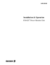
22. At the “Enter Channel Number” prompt, type the
channel number of the transmitter and press the Enter
key. The Analog Input Channel screen for that channel
should then appear on the terminal (see Figure 18). (If
item #10 - Channel Enable Method = 5, item #11 will
not be present.)
23. With the Analog Input Channel screen shown on the
terminal, type 1 (for item #1 - Channel Type) and press
the Enter key.
24. At the “Enter New Data” prompt, type 3 and press the
Enter key. The screen will be re-written to add item #11
(or #12) - Antenna Channel (see Figure 19).
25. Type 11 or 12 (whichever corresponds to the Antenna
Channel) and press the Enter key.
26. At the “Enter New Data” prompt, type AI025 for
antenna #1 or AI027 for antenna #2, and press the Enter
key. The screen will be re-written to show the new
value.
27. Type E (to End programming this channel) and press
the Enter key. The Setup Selection Menu should then
appear on the terminal.
This completes the configuration of the Antenna
Channel parameter for the selected transmitter. If this
parameter needs to be changed for another transmitter,
return to step 21. When this parameter is satisfactory for all
transmitters, go on to step 28.
ANALOG INPUT CHANNEL 1
1. CHANNEL TYPE (0-13) = 0
2. DESCRIPTION = TX01
3. UNIT ID = AI01
4. MEASUREMENT UNITS = Watts
5. ALARM DELAY (1/4 sec) = 3
6. LOWER ALARM LIMIT = 0.0
7. UPPER ALARM LIMIT = 125.0
8. ALARM REPORT TYPES (1,2,3,4) =
9. ALARM RELAY NUMBER = 0
10. CHANNEL ENABLE METHOD (0-5) = 0
11. CHANNEL ENABLE THRESHOLD = 0.0
ENTER ITEM NUMBER TO CHANGE,
"H" FOR HELP MENU, "A" TO ABORT,
OR "E" TO END PROGRAMMING THIS CHANNEL:
Figure 18 - Analog Input Channel Screen