LBI-39128 MAINTENANCE
32
1. With the Operation Select Menu (main menu) shown on
the screen, type 2 (for item #2 - Reports) and press the
Enter key. The Report Selection Menu should then
appear on the terminal as shown in Figure 23.
2. Type 5 (for item #5 - Channel Monitor) and press the
Enter key.
3. At the “Monitor Unit ID (Y/N)?” prompt, press the
Enter key (you do not need to type Y or N).
4. At the “Enter Channel Number (Enter to begin
monitoring):” prompt, type a channel number from
Table 9 (note that the zeros between AI or AP and the
number may be omitted as shown), wait until the
transmitter or antenna of interest is in use, and then
quickly press the Enter key twice.
Table 9 - Channel Numbers for Channel Monitor Screen
CHANNEL
NUMBER
SENSOR
LOCATION
CALCULATED
VALUE
AI1
↕
AI20
Transmitter #1
↕
Transmitter #20
Forward Power
↕
Forward Power
AI25 Antenna #1 Forward Power
AI26 Antenna #1 Reflected Power
AI27 Antenna #2 Forward Power
AI28 Antenna #2 Reflected Power
AP1 Antenna #1 SWR
AP2 Antenna #2 SWR
5. If the message “*** Channel Not Programmed ***”
appears on the line following your channel number
entry, the transmitter or antenna selected was not in use.
Repeat step 4 until the Channel Monitor screen is
shown on the terminal.
The screen will automatically time out after 15 minutes
and display the “press any key to continue monitoring”
prompt. If you press any key within the 20 second grace
period, the screen will continue for another 15 minutes. If
you do nothing, the Report Selection Menu will appear at
the end of the grace period. At any time you may press the
Esc key to return to the Report Selection Menu.
SOFTWARE UPDATES
Don’t forget to redo any necessary programming
(including antenna mapping). See the Programming heading
in the Installation section.
If it becomes necessary to update the system software in
the PMU, use the following procedure. This will undo all
programming by the user (including antenna mapping during
installation).
1. Switch the PMU’s On-Off switch to the off position.
2. Label and disconnect all cables and wires connected to
the PMU.
3. Remove the PMU from the cabinet and remove the top
cover.
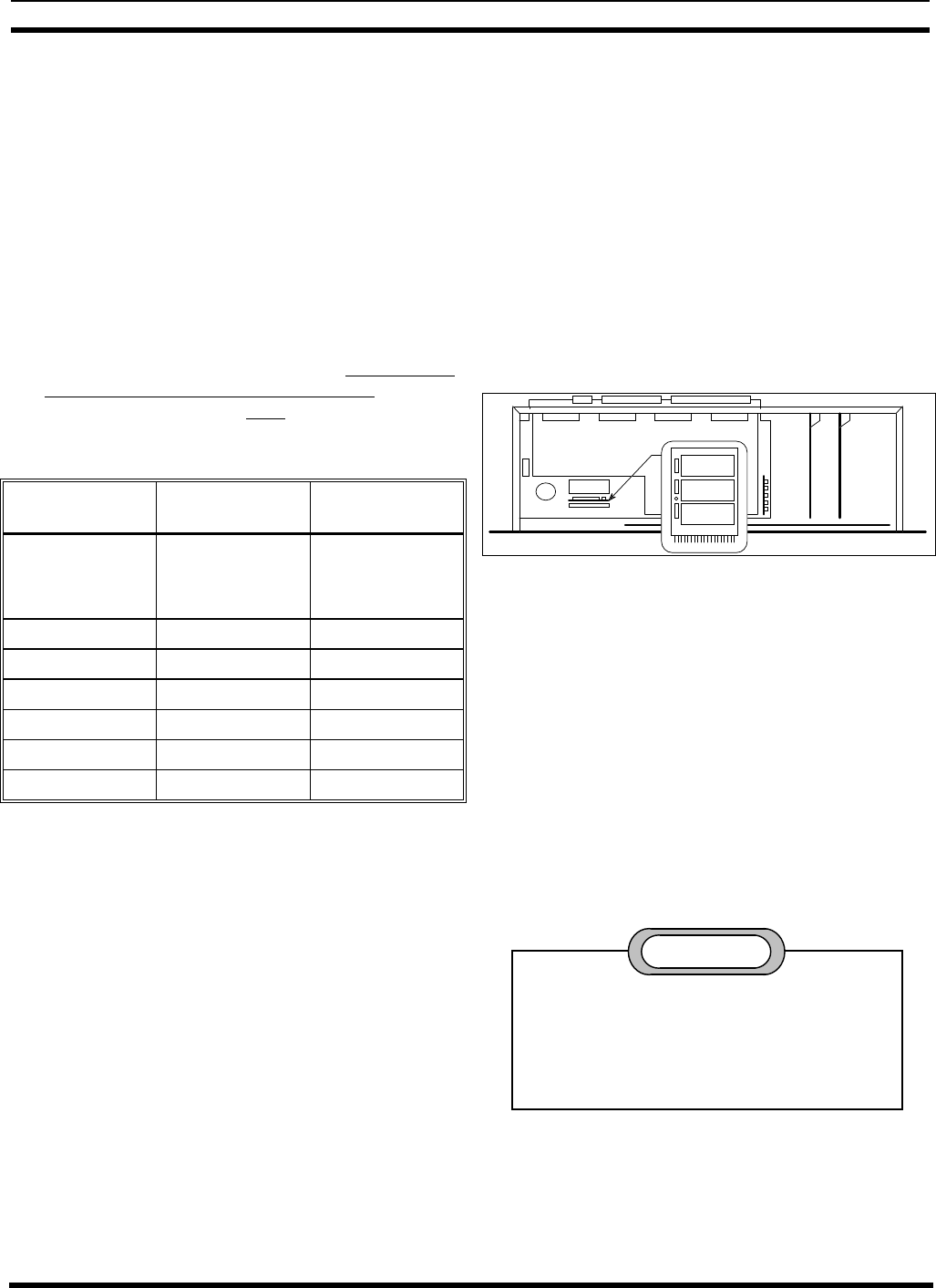
4. Remove the board with the three PROMs labeled “F”,
“E”, and “D” as shown in Figure 26.
PROM 2 "F"
PROM 1 "E"
PROM 0 "D"
Figure 26 - Location of PMU Software
5. Replace the three PROMs, being careful to orient them
correctly in the correct socket.
6. Return the board with the three PROMs to the second
connector from the front of the PMU, with the
components facing the back of the PMU.
7. Make sure that the program data in the PMU is set to
the factory default values by performing a Hardware
Reset (see next heading). Start at step #4 and continue
to the end.
ERASE ALL PROGRAMMING
Performing a Hardware Reset (power-up), with
DIP switch #1 in the on position, will return the
PMU’s parameters to the factory default values.
This will erase all user programming (including
antenna mapping during installation).
CAUTION
If the password has been changed from the factory
default and you cannot remember it, you must erase all
programming in order to regain programming access to the
PMU. After erasing all programming, the password will be
its default value of 8860. If you know the password and just
