


LBI-39128 OPERATION
22
OPERATION
The PMU performs the following operations:
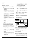
• Monitors the detector output voltages from the
transmitter and antenna power sensors under the
direction of the Site Controller computer.
• Converts the detector output voltages to power and
SWR levels.
• Compares the power and SWR levels to user-
configurable alarm threshold limits.
• Sets the power alarm status for each monitored
transmitter and antenna.
• Reports the power alarm status of each transmitter
and antenna to the Site Controller computer.
The Site Controller computer performs the following
operations:
• Tells the PMU which transmitter channels to
monitor.
• Tells the PMU when each transmitter starts and
stops transmitting.
• Uses the power alarm status to help determine
which transmitter channels are useable.
• Uses the power alarm status to control the ANT
PWR FAIL and CHN PWR FAIL indicators on the
Alarm and Control Unit (if present in the system).
• Uses the power alarm status to direct Test Calls by
the Test Unit (if present in the system).
• Reports the power alarm status to the System
Manager (if present in the system).
STARTUP
Directions from the Site Controller computer to the
PMU, and reports of power alarm status from the PMU to
the Site Controller computer, are sent over the serial data
link connecting the two.
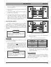
Polling Recovery
As soon as the Site Controller computer is operating
(power on and initialization complete) and the parameter
that enables the PMU option is enabled (initialized from the
Personality PROMs or re-configured from the System
Manager), it should start sending a poll message to the PMU
once each second (even if the PMU doesn’t reply or isn’t
connected).
As soon as the PMU is operating (power on), it should
start looking for messages from the Site Controller computer
(even if the Site Controller computer isn’t sending a poll
message or isn’t connected). As soon as it receives a poll
message, it should reply with a status message within one
second.
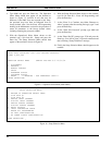
EDACS Configuration Setup
After receiving five consecutive status message
responses (each within one second) to five consecutive poll
messages, the Site Controller computer should send the
EDACS Configuration Setup information to the PMU. This
information consists of which transmitter channel numbers
are PMU enabled, and the low alarm limit for each
transmitter channel number.
After receiving the EDACS Configuration Setup
information, the PMU should be ready to monitor the
transmitter and antenna power sensors under the direction of
the Site Controller computer. The Site Controller computer
should continue to send a poll message to the PMU once
each second, and the PMU should continue to reply with a
status message within one second of each poll message.
Polling Failure
If at any time the PMU fails to reply to a poll message
within one second, or the Site Controller computer is
initialized (by reset or power-up), the Site Controller
computer must again receive five consecutive replies and
send the EDACS Configuration Setup information before
the PMU is again ready to monitor the power sensors.
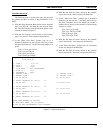
MONITOR
Power Sensor Monitoring
When the PMU is ready to monitor the power sensors,
the Site Controller computer sends a message to the PMU
each time a transmitter is keyed or unkeyed. The message
tells the PMU which transmitters are keyed (transmitting),
and which are not. From the EDACS Configuration Setup
information and the user-configured PMU parameters, the
PMU determines which keyed transmitter channel numbers
are PMU enabled, which sensors to monitor, what
calculations to make, and what alarm limits to use.
Every 250 milliseconds the PMU should measure all
analog inputs associated with all PMU enabled keyed