


INSTALLATION LBI-39128
13
Power Sensor interface module connector marked “J1”,
label the cable “J1” and disconnect it from the Power
Sensor interface module.
11. If a cable (or an existing 19C852379G1 Channel
Termination Board) is connected to the Power Sensor
interface module connector marked “J2”, label the cable
(or board) “J2” and disconnect it at the Power Sensor
interface module.
12. Find the cables (or group of cables) connected to the
Power Sensor interface module connectors marked “J6”
and “J7”, determine which cable (or group of cables)
goes to some point outside the cabinet, label this cable
(or group of cables) “J9” (the connector number on the
new Power Sensor interface module is different), and
disconnect this cable (or group of cables) at the Power
Sensor interface module.
13. Remove the old 19C852213G1 Power Sensor interface
module and all cables still connected to it (all cables
still connected to it should have been disconnected at
their other end in step #5).
14. Mount the new 19C852632G1 Power Sensor interface
module in the space vacated by the old module.
15. Connect the existing cables (or board) labeled “J1”,
“J2”, and “J9” in steps 10-12 to the connectors marked
“J1”, “J2”, and “J9” respectively on the new Power
Sensor interface module.
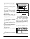
16. Connect the 5 new 188D6466P2 cables from J3 through
J7 on the new Power Sensor interface module to Port 1
through Port 5, respectively, on the back of the new
PMU.
17. Connect the new 188D6466P1 cable from J8 on the
new Power Sensor interface module to Port 7 on the
back of the new PMU (skip Port 6).
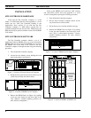
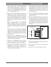
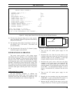
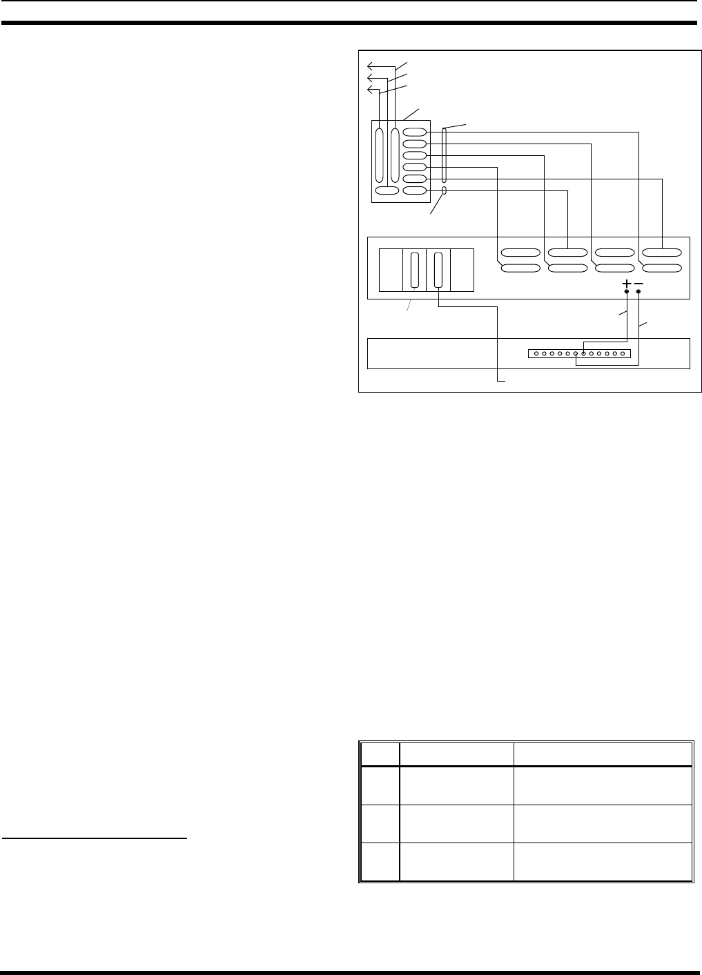
18. Double check the installation using the interconnection
diagram shown in Figure 11.
19. Set the power switch on the back of the PMU to the
“Off” position.
20. Turn on the main 12V power supply for the cabinet.
C. Adaptation from Old PMU
Use this procedure only if your Site Controller cabinet
doesn’t have EDACS Interface panels, but does have an old
PMU.
J1 J2
J3
J4
J5
J6
J7
J8J9
188D6466P2 Cables (5 Each)
PORT 7 PORT 5
188D6466P1 Cable
PORT 8 PORT 6
Daisy Chain Cable to Power Sensors for Transmitter Channels 1 - 12
Daisy Chain Cable to Power Sensors for Transmitter Channels 11 - 20
Antenna Power Sensor Cable to Power Sensors for Antennas 1 & 2
19C852632G1 POWER SENSOR INTERFACE MODULE
POWER MONITOR UNIT
PORT 1PORT 4 PORT 2PORT 3
#18 Red
#18 Black
Terminal
Connection
DOWNLINK GETC
112
6
7
Existing Cable To Site Controller Computer
Programming
VDT Interfaces
Figure 11 - Connections for Upgrade from Old PMU
This procedure consists of replacing the old PMU with
the new PMU, adding an adapter cable between the existing
transmitter power sensor cables and the new PMU, and
adding an adapter cable between the existing antenna power
sensor cable and the new PMU. The existing RS232 data
link to the Site Controller computer and the two DC power
wires can be re-connected directly to the new PMU. This
procedure upgrades the system to the extent that it adds the
new PMU, but uses adapter cables instead of upgrading to
the EDACS Interface Panel configuration.
Parts Required
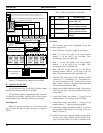
Before you start this procedure, be sure you have all the
parts on hand. The parts for this procedure are shown in
Table 4.
Table 4 - Parts for Adaptation from Old PMU
QTY PART # DESCRIPTION
1 350A1380P1 Decibel Products DB8860-
based PMU Unit
1 188D6451P1 Adapter Cable - Transmitter
power sensor circuits
1 188D6496P1 Adapter Cable - Antenna
power sensor circuits