


INSTALLATION LBI-39128
21
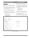
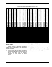
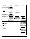
Table 6 - Power Sensor Voltage-to-Power Conversion Table
VP VP VP VP VP VP VP VP
0.00 0.0 0.62 25.5 1.25 80.6 1.87 164.4 2.50 276.7 3.13 417.2 3.76 585.9 4.38 782.7
0.01 0.6 0.64 26.8 1.27 82.8 1.89 167.5 2.52 280.6 3.15 422.0 3.77 591.6 4.40 789.3
0.03 1.0 0.66 28.1 1.28 85.0 1.91 170.6 2.54 284.6 3.17 426.9 3.79 597.4 4.42 795.9
0.05 1.4 0.68 29.5 1.30 87.2 1.93 173.7 2.56 288.6 3.19 431.8 3.81 603.1 4.44 802.5
0.07 1.8 0.70 30.8 1.32 89.5 1.95 176.9 2.58 292.7 3.22 436.7 3.83 608.9 4.46 809.2
0.09 2.2 0.72 32.2 1.34 91.8 1.97 180.1 2.60 296.8 3.23 441.7 3.85 614.8 4.48 815.9
0.11 2.7 0.74 33.6 1.36 94.1 1.99 183.3 2.62 300.9 3.25 446.7 3.87 620.6 4.50 822.7
0.13 3.2 0.76 35.1 1.38 96.5 2.01 186.5 2.64 305.0 3.27 451.7 3.89 626.5 4.52 829.4
0.15 3.7 0.77 36.6 1.40 98.8 2.03 189.8 2.66 309.2 3.28 456.7 3.91 632.4 4.54 836.2
0.17 4.3 0.79 38.1 1.42 101.3 2.05 193.1 2.68 313.3 3.30 461.8 3.93 638.4 4.56 843.0
0.19 4.9 0.81 39.6 1.44 103.7 2.07 196.4 2.70 317.5 3.32 466.9 3.95 644.4 4.58 849.9
0.21 5.5 0.83 41.2 1.46 106.2 2.09 199.8 2.72 321.8 3.34 472.0 3.97 650.4 4.60 856.8
0.23 6.1 0.85 42.8 1.48 108.7 2.11 203.2 2.74 326.1 3.36 477.2 3.99 656.4 4.62 863.7
0.25 6.8 0.87 44.4 1.50 111.2 2.13 206.6 2.75 330.4 3.38 482.3 4.01 662.4 4.64 870.6
0.27 7.5 0.89 46.0 1.52 113.7 2.15 210.0 2.77 334.7 3.40 487.5 4.03 668.5 4.66 877.6
0.28 8.3 0.91 47.7 1.54 116.3 2.17 213.5 2.79 339.0 3.42 492.8 4.05 674.6 4.68 884.5
0.30 9.1 0.93 49.4 1.56 118.9 2.19 217.0 2.81 343.4 3.44 498.0 4.07 680.8 4.70 891.5
0.32 9.9 0.95 51.2 1.58 121.5 2.21 220.5 2.83 347.8 3.46 503.3 4.09 686.9 4.72 898.6
0.34 10.7 0.97 52.9 1.60 124.2 2.23 224.1 2.85 352.2 3.48 508.6 4.11 693.1 4.74 905.7
0.36 11.6 0.99 54.7 1.62 126.9 2.25 227.6 2.87 356.7 3.50 514.0 4.13 699.3 4.76 912.7
0.38 12.5 1.01 56.5 1.64 129.6 2.27 231.2 2.89 361.2 3.52 519.3 4.15 705.6 4.77 919.9
0.40 13.4 1.03 58.4 1.66 132.4 2.28 234.9 2.91 365.7 3.54 524.7 4.17 711.9 4.79 927.0
0.42 14.4 1.05 60.3 1.68 135.1 2.30 238.5 2.93 370.3 3.56 530.2 4.19 718.2 4.81 934.2
0.44 15.3 1.07 62.2 1.70 137.9 2.32 242.2 2.95 374.8 3.58 535.6 4.21 724.5 4.83 941.4
0.46 16.4 1.09 64.1 1.72 140.8 2.34 245.9 2.97 379.4 3.60 541.1 4.23 730.8 4.85 948.6
0.48 17.4 1.11 66.1 1.74 143.6 2.36 249.7 2.99 384.0 3.62 546.6 4.25 737.2 4.87 955.9
0.50 18.5 1.13 68.0 1.76 146.5 2.38 253.5 3.01 388.7 3.64 552.1 4.27 743.6 4.89 963.2
0.52 19.6 1.15 70.1 1.77 149.4 2.40 257.3 3.02 393.4 3.66 557.7 4.28 750.1 4.91 970.5
0.54 20.7 1.17 72.1 1.79 152.4 2.42 261.1 3.05 398.1 3.68 563.3 4.30 756.5 4.93 977.8
0.56 21.9 1.19 74.2 1.81 155.3 2.44 264.9 3.07 402.8 3.70 568.9 4.32 763.0 4.95 985.2
0.58 23.1 1.21 76.3 1.83 158.3 2.46 268.8 3.09 407.6 3.72 574.5 4.34 769.5 4.97 992.6
0.60 24.3 1.23 78.4 1.85 161.3 2.48 272.7 3.11 412.4 3.74 580.2 4.36 776.1 4.99
FINAL CHECK
Before the installation is complete, the Site Controller
computer must be re-connected and the PMU option given a
final operational check.
1. Re-connect the data link cable from the Site Controller
computer to the right-hand VDT Interface connector on
the back of the PMU (cable was temporarily
disconnected for initial power-up and antenna
mapping).
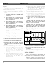
2. Verify that the “PWR” indicator on the front panel of
the PMU stays on continuously.
3. Verify that the three other indicators on the front panel
of the PMU are flashing in a repeating sequence. The
“MUX” indicator should flash once every 250
milliseconds; first by itself, next with the “DATA”
indicator, and then with the “ALARM” indicator.