LBI-39128 INSTALLATION
12
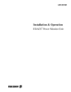
J1 J2
J3
J4
J5
J6
J7
J8J9
188D6466P2 Cables (5 Each)
PORT 7 PORT 5
188D6466P1 Cable
PORT 8 PORT 6
Daisy Chain Cable to Power Sensors for Transmitter Channels 1 - 12
Daisy Chain Cable to Power Sensors for Transmitter Channels 11 - 20
Antenna Power Sensor Cable to Power Sensors for Antennas 1 & 2
19C852632G1 POWER SENSOR INTERFACE MODULE
POWER MONITOR UNIT
PORT 1PORT 4 PORT 2PORT 3
#18 Red
#18 Black
Terminal
Connection
SITE CONTROLLER
Use 19D903880P101 Cable If
112
6
7
Port 29
COMPUTER
DILOG DILOG
Connecting to DILOG Panel
13B
Use 19D903880P100 Cable If
0511 0511AB
Connecting to Site Controller Computer
Programming
VDT Interfaces
DOWNLINK GETC
(TRUNKING CARD)
Figure 10 - Connections for Addition from No PMU
B. Upgrade from Old PMU
Use this procedure only if your Site Controller cabinet
has EDACS Interface panels and an old PMU.
This procedure consists of upgrading the Site Controller
by replacing the old PMU, replacing the old Power Sensor
interface module, and replacing the cables between them.
Parts Required
Before you start this procedure, be sure you have all the
parts on hand. The parts for this procedure are shown in
Table 3.
Table 3 - Parts for Upgrade from Old PMU
QTY PART # DESCRIPTION
1 350A1380P1 Decibel Products DB8860-
based PMU Unit
1 188D6466P1 Cable - PMU to Power
Sensor interface module
5 188D6466P2 Cable - PMU to Power
Sensor interface module
1 19C852632G1 Power Sensor interface
module
Procedure
The following steps involve equipment in the Site
Controller cabinet only:
1. Turn off the main 12V power supply for the cabinet.
2. Mark “+” on the wire going to the screw terminal
marked “+” on the back of the old PMU. Then
disconnect this wire at the PMU end.
3. Mark “–” on the wire going to the screw terminal
marked “–” on the back of the old PMU. Then
disconnect this wire at the PMU end.
4. Mark “RS-232” on the cable going to the DB-25
connector marked “RS-232” on the back of the old
PMU. Then disconnect this cable at the PMU end.
5. Disconnect any cables going to the connectors marked
“Antennas 1-4”, “Transmitters 1-9”, “Transmitters 10-
18”, and “Transmitters 19-20” on the back of the old
PMU. (There is no need to label these cables since they
will not be used with the new PMU.)
6. Replace the old PMU with the new PMU. There will be
a half rack unit space (7/8 inch) both above and below
the new PMU.
7. Connect the existing wire labeled “+” in step 2 to the
terminal labeled “+” on the back of the new PMU.
8. Connect the existing wire labeled “–” in step 3 to the
terminal labeled “–” on the back of the new PMU.
9. Connect the existing cable labeled “RS232” in step 4 to
the right-hand VDT interface on the back of the new
PMU (see Figure 7).
10. Find the Power Sensor interface module mounted in the
left end of the upper EDACS Interface Panel in the
upper rear of the cabinet. If a cable is connected to the