


LBI-39128 INSTALLATION
10
Parts Required
Before you start this procedure, be sure you have all the
parts on hand. The parts for this procedure are shown in
Table 2.
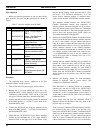
Table 2 - Parts for Addition from No PMU
QTY PART # DESCRIPTION
1 19D903880P100
or
19D903880P101
Cable - DILOG Panel to
PMU
Cable - Site Controller
computer to PMU
1 350A1380P1 Decibel Products DB8860-
based PMU Unit
1 188D6466P1 Cable - PMU to Power
Sensor interface module
5 188D6466P2 Cable - PMU to Power
Sensor interface module
1 19C852632G1 Power Sensor interface
module
1 19C852677P1 Cable - Power Sensor
interface module to Antenna
power sensor(s)
1 or
2
19C336861P3
or
19C336861P4
Antenna power sensor (450
- 1000 MHz)
Antenna power sensor (66 -
325 MHz)
Procedure
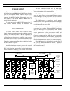
The following steps involve equipment in the Site
Controller cabinet, except as noted:
1. Turn off the main 12V power supply for the cabinet.
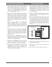
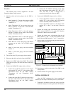
2. Replace the 5 1/4 inch blank panel just above the
Downlink GETC (called Trunking Card in some older
installations) with the PMU. There will be a half rack
unit space (7/8 inch) both above and below the PMU.
3. Connect the #18 red wire from the terminal on the back
of the PMU labeled “+”, to TB10-7 on the back of the
Downlink GETC shelf.
4. Connect the #18 black wire from the terminal on the
back of the PMU labeled “–”, to TB10-6 on the back of
the Downlink GETC shelf.
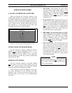
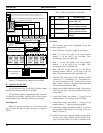
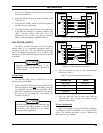
5. Mount the new 19C852632G1 Power Sensor interface
module on the left-hand end of the upper EDACS
Interface Panel in the upper rear of the cabinet, using
the four thread forming screws provided with it. (You
will need a T15 Torx-head screwdriver.) If an old
Power Sensor interface module is mounted there,
replace it with the new 19C852632G1 interface module.
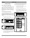
This interface module contains two 19C852379G1
Channel Termination Boards, each containing 12
shorting jumpers. The board plugged into J1 is used to
short any unused power sensor circuit for Transmitter
channels #1 through #12. The board plugged into J2 is
used to short any unused power sensor circuit for
Transmitter channels #11 through #20.
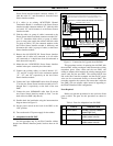
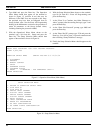
6. Remove the 19C852379G1 Channel Termination Board
from J1 on the Power Sensor interface module (installed
in step 5), and connect a 25-pair cabinet interconnect
cable in its place. Connect the other end of the 25-pair
cabinet interconnect cable to J14 or J15 on the Power
Sensor interface module in the EDACS Repeater
cabinet containing the transmitter for channel #1). If the
two cabinets are next to each other in the same row, use
a 5-ft 19D903880P120 cable. If the two cabinets are
across from each other in different rows, use a 15-ft
19D903880P121 cable.
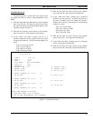
7. Starting with the cabinet containing the transmitter for
channel #1, follow the daisy chain of 25-pair cabinet
interconnect cables connected to J14 and J15 on the
Power Sensor interface module in each EDACS
Repeater cabinet until an empty J14 or J15 connector is
found. Plug the 19C852379G1 Channel Termination
Board (removed in the previous step) into this empty
connector.
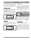
8. Remove the shorting jumper for each transmitter
channel # equipped with a power sensor (P#
corresponds to transmitter channel #).
Note that there is a shorting jumper for transmitter
channels #11 and #12 on each of the 19C852379G1
Channel Termination Boards. Therefore, if transmitter
channel #11 or #12 is equipped with a power sensor, a
jumper must be removed from each of the two channel
termination boards.
9. If the system does not have any additional EDACS
Repeater cabinets not included in the daisy chain in the
previous step, go to step 11.
If the system has additional EDACS Repeater cabinets
not included in the daisy chain in the previous step,
remove the 19C852379G1 Channel Termination Board
from J2 on the Power Sensor interface module (installed
in step 5), and connect a 25-pair cabinet interconnect
cable in its place. Connect the other end of the 25-pair
cabinet interconnect cable to J14 or J15 on the Power