6
INTRODUCTION
This manual describes the installation and operation of
the Decibel Products DB8860-based PMU (Power Monitor
Unit) for non-simulcast EDACS (Enhanced Digital Access
Communications System) repeater sites that use a VAX
computer for the Site Controller. This manual covers only
those features of the Decibel Products DB8860 that are
required for this application.
The user must provide an RS232 CRT terminal (or PC
with terminal emulation software) for installation and
maintenance.
DESCRIPTION
The PMU (Power Monitor Unit) is used to quickly
identify damaged transmitters, transmit combiners, transmit
antennas, and connecting cables so that the equipment can
be quickly removed from service and repaired. The PMU is
a microprocessor-driven power monitoring and reporting
device that receives power measurements from the power
sensors, receives monitoring instructions from the Site
Controller computer, and reports alarm conditions back to
the Site Controller computer.
A unidirectional power sensor is placed at the output of
each transmitter to send forward power measurements to the
PMU. A bi-directional power sensor is placed at the output
of each transmitter combiner to send forward and reflected
power measurements to the PMU.
The Site Controller computer tells the PMU which
power sensors to monitor and when, by telling the PMU
when each transmitter is keyed and unkeyed.
The PMU reports an alarm for a specific transmitter
when the output power measurement for that transmitter
exceeds the upper or lower power limit. The Site Controller
computer then takes that transmitter out of service.
The PMU reports an alarm for a specific antenna
number when the input power measurement for that antenna
exceeds the upper or lower power limit, or the SWR
calculation exceeds the upper limit.
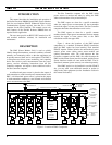
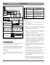
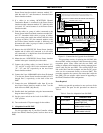
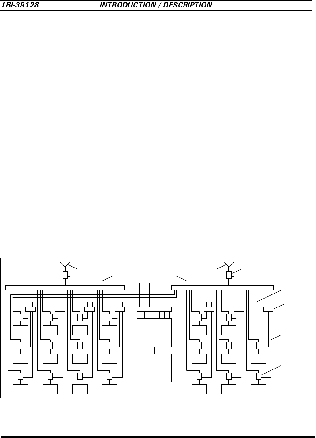
Figure 1 shows the locations of the PMU-related
components in a standard 20-channel EDACS installation
after the PMU option has been installed. Each standard
EDACS repeater cabinet includes the unidirectional power
sensors, power sensor cables, power sensor module, and
cabinet interconnect cable. The cable between the Site
Controller computer and the PMU, the cables between the
PMU and the Power Sensor interface module, and the Power
Sensor interface module all come with the PMU. The bi-
directional (antenna) power sensor(s) are ordered separately.
If the PMU option is to be installed in an older EDACS
site, you may need some additional material to update or
adapt to the older equipment (see the Installation section in
this manual for details).
Antenna #1
Xmtr
#12
Antenna #2
Controller
Xmtr
#11
Xmtr
#10
Xmtr
#9
Xmtr
#8
Xmtr
#7
Xmtr
#6
Xmtr
#5
Xmtr
#4
Xmtr
#3
Xmtr
#2
Xmtr
#1
Xmtr
#15
Xmtr
#14
Xmtr
#13
Xmtr
#18
Xmtr
#17
Xmtr
#16
Xmtr
#20
Xmtr
#19
Transmitter Combiner #2Transmitter Combiner #1
Power
Power Sensor
Module
Unidirectional
Power
Sensor
Power
Bi-directional
Sensor
Unit
Monitor
Computer
Site
Power Sensor
Cable
Transmitter
Cabinet
Interconnect
Cable
Antenna Power Sensor Cable
Interface Module
Interface
Figure 1 - Location of PMU Components


