INSTALLATION LBI-39128
19
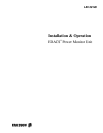
ANALOG INPUT CHANNEL 1
1. CHANNEL TYPE (0-13) = 3
2. DESCRIPTION = TX01
3. UNIT ID = AI01
4. MEASUREMENT UNITS = Watts
5. ALARM DELAY (1/4 sec) = 3
6. LOWER ALARM LIMIT = 0.0
7. UPPER ALARM LIMIT = 125.0
8. ALARM REPORT TYPES (1,2,3,4) =
9. ALARM RELAY NUMBER = 0
10. CHANNEL ENABLE METHOD (0-5) = 0
11. CHANNEL ENABLE THRESHOLD = 0.0
12. ANTENNA CHANNEL = AI025
ENTER ITEM NUMBER TO CHANGE,
"H" FOR HELP MENU, "A" TO ABORT,
OR "E" TO END PROGRAMMING THIS CHANNEL: _
Figure 19 - Analog Input Channel Screen Showing Antenna Channel Parameter
28. With the Setup Selection Menu shown on the terminal,
type 1 (for item #1 - Return To Operation Select Menu)
and press the Enter key.
29. The Operation Select Menu should then be shown on
the terminal. Type 1 (for item #1 - Disconnect) and
press the Enter key.
30. The “Disconnected - Hit Any Key To Connect” prompt
should then appear on the terminal.
POWER SENSOR CALIBRATION
The power sensor provides a DC voltage output
representing the power through it. This calibration method
uses an in-line wattmeter to read the power going through
the power sensor, a DC voltmeter to measure the DC voltage
out of the power sensor, and a conversion table to simulate
the PMU’s calculation of power from this DC voltage. This
DC voltage is then adjusted (using the 20-turn potentiometer
mounted in the power sensor) until the power read from the
conversion table agrees with the power read on the power
meter.
Unidirectional Power Sensors
Use the following procedure to calibrate the
unidirectional power sensors used at the output of each
transmitter. Start with the transmitter for channel #1. The
location of the calibration screw is shown in Figure 20.
Calibration Screw
Figure 20 - Unidirectional Power Sensor Calibration Screw
1. Turn off the 12V station power supply for the
transmitter.
2. Disconnect the coax (from the power sensor to the
combiner) at the power sensor end, and insert an in-line
wattmeter (make sure the wattmeter is rated high
enough to handle the power from the transmitter).
3. Disconnect the power sensor cable from the phono
connector on the power sensor, and attach the DC
voltmeter in its place (center pin is positive). (An
alternate method is to disconnect the power sensor cable
at the PMU - see interconnection diagram at end of
manual - and attach the DC voltmeter to the end of the
cable.)
4. Turn on the 12V station power supply for the
transmitter.
5. Manually key the transmitter using the switch marked
“REM KEY”, or press and hold the PTT switch on a
hand-held microphone plugged into the transmitter.
6. Measure the DC voltage on the meter, look up this
voltage in Table 6 (V in volts) to get the corresponding