


LBI-39128 INSTALLATION
20
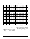
power (P in watts), and compare with the actual power
measurement on the power meter. Because the table
does not contain all values of V and P, you may need to
interpolate to get the values you need.
7. Turn the calibration screw (clockwise if the measured
power is lower than the power from the table) and
repeat steps 6 and 7 until the measured power is the
same as the power from the table.
8. Turn off the 12V station power supply for the
transmitter.
9. Disconnect the DC voltmeter from the phono connector
on the power sensor, and re-connect the power sensor
cable in its place.
10. Remove the wattmeter from between the power sensor
and the coax to the combiner, and re-connect the coax
to the power sensor.
11. Turn on the 12V station power supply for the
transmitter.
12. Repeat steps 1 through 11 for the next transmitter until
each transmitter has had its power sensor calibrated.
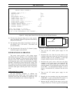
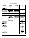
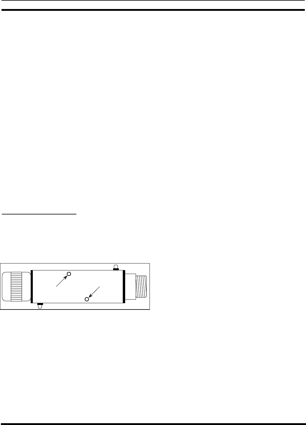
Bi-directional Power Sensors
Use the following procedure to calibrate the bi-
directional power sensors used at the output of each
combiner. Start with the combiner that feeds antenna #1.
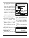
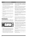
The locations of the calibration screws are shown in Figure
21.
Calibration Screw
Calibration Screw
Forward Power
Reflected Power
Forward Power
Reflected Power
Figure 21 - Bi-directional Power Sensor Calibration Screws
1. Disconnect the coax (from the power sensor to the
antenna) at the power sensor end, and insert an in-line
wattmeter set to measure forward power (make sure the
wattmeter is rated high enough to handle the power
from all the transmitters feeding the combiner).
2. Disconnect the power sensor cable from the phono
connector for the forward power on the power sensor,
and attach the DC voltmeter in its place (center pin is
positive). (An alternate method is to disconnect the
power sensor cable at the PMU - see interconnection
diagram at end of manual - and attach the DC voltmeter
to the end of the cable.)
3. Manually key the transmitter using the switch marked
“REM KEY”, or press and hold the PTT switch on a
hand-held microphone plugged into the transmitter.
4. Measure the DC voltage on the meter, look up this
voltage in Table 6 (V in volts) to get the equivalent
power calculation (P in watts), and compare with the
actual power measurement on the power meter.
5. Turn the calibration screw (clockwise if the measured
power is lower than the power from the table) and
repeat steps 4 and 5 until the measured power is the
same as the power from the table.
6. Disconnect the DC voltmeter from the phono connector
on the power sensor, and re-connect the power sensor
cable in its place.
7. Set the in-line wattmeter to measure reflected power.
8. Disconnect the power sensor cable from the phono
connector for the forward power on the power sensor,
and attach the DC voltmeter in its place (center pin is
positive).
9. Manually key the transmitter using the switch marked
“REM KEY”, or press and hold the PTT switch on a
hand-held microphone plugged into the transmitter.
10. Measure the DC voltage on the meter, look up this
voltage in Table 6 (V in volts) to get the equivalent
power calculation (P in watts), and compare with the
actual power measurement on the power meter.
11. Turn the calibration screw (clockwise if the measured
power is lower than the power from the table) and
repeat steps 10 and 11 until the measured power is the
same as the power from the table.
12. Disconnect the DC voltmeter from the phono connector
on the power sensor, and re-connect the power sensor
cable in its place.
13. Remove the wattmeter from between the power sensor
and the coax to the combiner, and re-connect the coax
to the power sensor.
14. Repeat steps 1 through 13 for the other combiner (if two
transmit antennas are used).