


11.0 Maintenamce
NOTICE: Use of the material contained in this document is subject to the warning on page Iv and the disclaimer
on page v of this document.
DOC012R02 AOC 15/50 User Manual Nov 2001
90
The following sections contain the maintenance routines for the AOC 15/50. Note that not all of
the maintenance listed has to be carried out at every scheduled check. See Appendix H for the
maintenance schedule and record sheets. The maintenance record sheet should be copied and
filled out for all maintenance and repairs carried out. See Appendix J for the fastener torque
requirements. Torques should be confirmed to 90% of the target value to ensure that bolts were
not loosened during inspection.
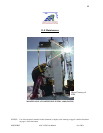
11.1 Rotor Assembly
Blades:
Blades should be cleaned thoroughly at intervals determined by local conditions (dust, salt,
insect loads, etc.) and after cases of severe contamination. The leading edge of each blade
should be inspected for surface and tape damage (i.e. cracks, dents, etc.) and the blade root
for cracking. The inspection and cleaning intervals can be adjusted to take environmental
conditions and variations in power production into account.
Tip Brakes:
Their deployment mechanism should be inspected and any faulty components should be
repaired or replaced as necessary. A pull test should be performed on each tip brake by
attaching a spring scale to the trailing edge of the tip brake plate and pulling on the scale at
right angels to the plate. The force at which the tip brake opens should be approximately 27
kg (60 lbs). The torque of the lock nuts holding the tip brakes to the blades should be
checked, as should that of the fasteners holding the clevises, hinge eyes and catch plate in
place; these fasteners must be snug tight and have Loctite 242 (Blue) applied. The magnet
and the catch plate should be cleaned if necessary. The spring/damper mechanism should be
inspected for smooth, even damping. The damper should also be checked for oil leaks,
which would indicate a defective damper, and that the spring is fully threaded onto the
spring retainer.
Hub:
All blade fasteners should be checked for proper torque (See Appendix J) and that their
washers are seated completely in the slot counter bores. If a washer is misaligned or turns
during the torque check, its bolt must be removed and replaced along with the washer. Take
care to seat the washer correctly.
Rotary Transformer:
The connections on both the rotating and the fixed transformer halves should be checked for
damage, such as corrosion, burn marks, melted insulation or breakage. The low speed shaft
and hub bore should be checked for score marks which would indicate slippage. This can
occur between the hub and the locking ring, as well as the locking ring and the shaft. The
casting should be checked for discoloration and the rotary transformer for dirt or debris. The
spacing (air gap) between the rotating and fixed transformer halves should be 0.5 - 1 mm
(0.020" - 0.040") and should be corrected if needed.