


6.0 Tower and Wind Turbine Generator Installation
NOTICE: Use of the material contained in this document is subject to the warning on page Iv and the disclaimer
on page v of this document.
DOC012R02 AOC 15/50 User Manual Nov 2001
36
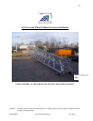
The following sections describe the assembly of the tower, as well as its erection and the
installation of the wind turbine generator.
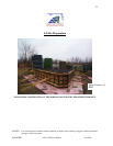
6.1 Tower Assembly
For the assembly details refer to the manufacturer’s instruction packet shipped with the tower.
The tower assembly drawings for the standard 24.4 m (80 ft) tower are supplied in Appendix C;
for those of the 30.5 m (100 ft) tower see Appendix D.
The tower will generally be assembled horizontally with two of its three legs near the ground.
Blocks should be used to support these two legs at several locations along their length. The
height of the blocks should be chosen to ensure that the tower is straight and to allow cross-
braces to be bolted to the legs. The blocks must have sufficient strength and stability for the
tower to be worked on safely.
After laying out the tower leg sections, the braces should be matched to their respective brace
clips on the legs. Braces and legs are clearly stamped with their part numbers and are referenced
in the tower drawings (see Appendix C or D). The bottom leg flanges of the bottom tower
section and the upper leg flanges of the topmost tower section are angled. This ensures that they
are parallel to the foundation and the turbine tower top casting once the tower is vertical.
The cross-braces between two legs from each section should be installed. The third leg then has
to be lifted above the two lower legs for the remaining cross-braces to be installed. The leg can
be raised using a bucket loader, fork lift or similar aid.
The open angle on the cross-braces should face towards the tower base, to shed any water. The
longer distance between the middle and the outer bolt hole in the cross-brace should also be
positioned facing down, towards the base. This configuration should be repeated down the tower
and around its sides. The top braces of each section start in the top hole of the brace clips, and
the bottom braces of each section terminate at the bottom hole of the brace clips. The cross-
brace holes may not line up with the brace clip hole easily but they can be aligned using a pair of
drift pins and two vise grips to hold the brace in place while a bolt is inserted.
Brace bolts should be installed with the head on the inside of the tower and the nut on the
outside. Flange bolts should be inserted from the bottom up, with the nut on the flange top. The
flange bolts on the top and bottom most sections should be left slightly loose until the tower is in
place, as should the cross-brace bolts on these sections. It is helpful to use templates on the top
and bottom sections when assembling the tower. This ensures a better fit when the tower is
erected on the foundation. The bolts on the middle sections may be tightened to their required
torques after the tower has been completely assembled.
The 1” flange bolt nuts should be torqued to 340 Nm (250 ft-lbs) and the 5/8” nuts on the braces,
to 200 Nm (150 ft-lbs). Pal nuts should be placed snug tight on every bolt after the nut has been
torqued, thereby indicating that the bolt has been torqued to specification.