


7.0 Electrical Installation
NOTICE: Use of the material contained in this document is subject to the warning on page Iv and the disclaimer
on page v of this document.
DOC012R02 AOC 15/50 User Manual Nov 2001
58
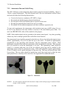
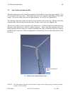
7.2.2 Anemometer Mast and Cable Wiring
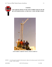
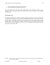
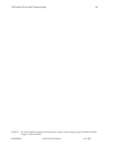
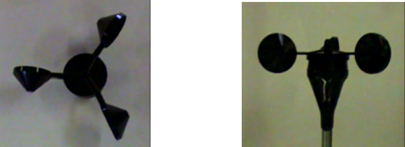
The AOC 15/50 uses a dual anemometer based control system for increased reliability. Figure 7-
3 shows a typical anemometer. The cable between each of the two anemometers and the control
enclosure must have the following characteristics:
• Consist of at least two conductors, #22 AWG or larger
• Be twisted and shielded against electrical interference
• Be resistant to ultraviolet radiation due to exposure on the tower
• Be rated for protected direct burial if not run in a conduit
• Be suitable for the ambient temperature and other conditions expected at site
To meet code requirements, the anemometer cable insulation must carry a 600V rating if it is to
be run for any distance in the same conduit or raceway as the wind turbine power cable. For
most sites BELDEN 9501 cable will be suitable for this purpose.
NOTE: Cable shields should only be grounded at the turbine control panel. Any other grounding
scheme may lead to multiple grounds that could affect circuit function.
The anemometer boom should be mounted at the third set of brace clips below the topmost tower
section, approximately 10 m (32 ft) from the top of the tower. It should be approximately
perpendicular to the prevailing wind direction, with the anemometer masts vertical. Each
anemometer should be fitted with one anemometer cable and attached to the mast. The cotter pin
has to be inserted to secure the anemometer to its mast. The anemometers cables should be
routed to a common point near one of the two adjacent tower legs and be attached to the
anemometer masts using UV protected tie wraps. Each cable should be looped, approximately
30 cm (12 inches) across, before attaching it to the tower leg. The loop will provide extra cable
for servicing. The two cables should be routed down one of the tower legs to either the twist
cable junction box or directly to the control box. See Appendix B for additional details.
Figure 7-3 Anemometer