


12.0 Troubleshooting
NOTICE: Use of the material contained in this document is subject to the warning on page Iv and the disclaimer
on page v of this document.
DOC012R02 AOC 15/50 User Manual Nov 2001
96
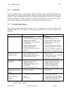
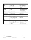
This section contains a brief discussion of each major wind turbine component and the control
system. See Section 12.7 for a summary of troubleshooting guidelines and recommendations.
When troubleshooting it can generally be assumed that only one fault exists. A failure can be
due to a malfunctioning component, one that still works but with reduced capacity, a broken
connection (mechanical or electrical), a set point which has drifted from its original calibration,
a loose or poor electrical connection, an improperly grounded cable shield or an intermittent
problem, i.e. one that can fall into any one of the previous categories after a certain period of
time.
Multiple failures can occur but are not typical and normally it will not be clear from the outset
whether a failure has single or multiple causes. The best course of action is to assume a single
failure and proceed to correct the obvious symptoms first. As troubleshooting progresses,
additional causes or failures can come to light.
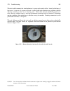
12.1 Braking System
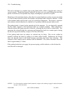
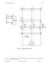
The braking system comprises three independent subsystems: the dynamic brake, the parking
brake and the tip brakes. The dynamic brake employs a resistive capacitive circuit to slow
rotation by dissipating rotational energy in the resistive network while maintaining some
excitation. During normal shutdowns the parking brake is delayed to prevent excessive loading
of the wind turbine transmission system. During emergency shutdowns the parking brake is
applied immediately and to prevent overloading of the turbine the dynamic brake is detuned by
switching out part of the capacitor circuit. The capacitor network consists of two distinct, relay
controlled stages and for a shutdown due to power loss, one stage of the capacitors will not be
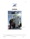
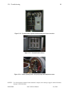
active. See Figures 12.1-1 to 12.1-4 for depictions of the brake systems.
The tip brakes are electro-magnetically controlled. The tip brake magnets receive their power
from the rotary transformer through a bridge rectifier located in each tip brake. Should the rotor
over-speed, power to the magnets is cut and the tip brake plates swing away from the blade end
due to centrifugal force, slowing the rotor down. Should a power loss occur in the grid, all three
braking systems (dynamic, tip, and parking brakes) deploy simultaneously.
Should all tip brakes deploy prematurely, their electric circuits should be checked, as well as the
rotary transformer, which could have developed a fault. If only one tip brake deploys
prematurely, its magnet’s setting should be checked, in addition to its electrical circuit. The
surfaces of both the magnet and catch plate should be checked for nicks, corrosion and debris.
Both must be smooth and flat for optimal operation. The vertical position of the magnet with
respect to the hinge block should also be checked. It can be adjusted using the threaded rod
attached to the magnet.
A deployed tip brake can also indicate a failure of a drive train component or of the dynamic
brake. Deformation of the tip brake plate could be caused by an excessive holding force, due to
a faulty magnet or corrosion, combined with rotor over-speed, heavy hailstone impact or by ice
being shed from the blades.