


9.0 Wind Turbine Operation
NOTICE: Use of the material contained in this document is subject to the warning on page Iv and the disclaimer
on page v of this document.
DOC012R02 AOC 15/50 User Manual Nov 2001
76
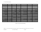
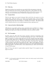
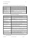
9.1.7.1 PLC Inputs
The following tables list and describe the input signals to the PLC controlling the AOC 15/50.
Function Description
Anemometer #1
0-5 VDC analog signal corresponds to 0-45 m/s (0-100 mph).
Anemometer #2
0-5 VDC analog signal corresponds to 0-45 m/s (0-100 mph).
Generator speed proximity
switches #1 and #2
Pulse input to F/V converter. 1-5 VDC signal corresponds to 0
to 2,000 rpm.
Watts Transducer Control
0-5 VDC analog signal corresponds to 0-8 kW.
Table 9.1-6 PLC low level analog inputs
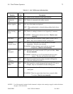
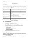
Function Description
Generator thermal switch
3 series connected switches within the generator.
Grid Voltage monitor
Relay contact indicating loss of phase, phase reversal and under
or over voltage.
Grid Frequency monitor
(optional)
Relay contact indicating over or under frequency.
Master control relay
Used to determine whether or not the turbine has been reset.
Turbine OFF/TEST/ON
Maintained switch parks or starts the turbine. In test position it
allows special test functions to become active.
Rotor jog switch
Maintained switch releases the brakes and connects the turbine
to the grid. Available in test mode.
Parking brake release switch
Maintained switch releases the parking brake. Available in test
mode.
Dynamic brake test switch
Maintained switch used in combination with the rotor jog
switch to delay operation of the tip and parking brakes to verify
the effectiveness of the dynamic brake. Available in test mode.
Remote start (optional)
Allows a turbine to be started by another turbine's controller; its
own anemometers (if equipped) are ignored.
Remote line start (optional)
Causes an across the line start if remote start is true.