


9.0 Wind Turbine Operation
NOTICE: Use of the material contained in this document is subject to the warning on page Iv and the disclaimer
on page v of this document.
DOC012R02 AOC 15/50 User Manual Nov 2001
72
9.1.4 Rotor Jog
With the wind turbine in test mode the rotor jog switch will allow the operator to release the
brakes and energize the main contactor, provided no high winds or fault conditions have been
registered. It is not necessary to use the parking brake release switch with the rotor jog, as the
rotor jog switch automatically releases all brakes before energizing the main contactor
9.1.5 Dynamic Brake
With the wind turbine in test mode, the dynamic brake switch allows the operator to test the
dynamic brake. When the switch is set to ON, only the dynamic brake is used for braking,
allowing its braking power to be observed. The dynamic brake test should be carried out only
during periods of low wind and be limited to a maximum of 10 seconds. The dynamic brake
resistors should be allowed to cool to ambient temperatures before repeating the test.
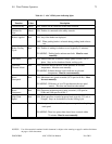
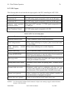
9.1.6 Operator Interface Indicating Lights
LED indicators are provided to indicate various wind turbine states (see Table 9.1-3). Unless a
manual reset is stated, the turbine will automatically reset once a fault has cleared. Meters
displaying wind speed, power output and wind turbine run time are available as options.
9.1.7 PLC Description
The PLC controls the AOC 15/50. The primary parameters measured for determining wind
turbine performance and control are wind speed and generator rotor speed. Each wind speed
signal is converted to an analog voltage and read by the PLC through analog input channels.
The wind turbine output power is determined by measuring the generator rpm and calculating
the power level based on rotor slip. The generator rotor speed is measured using two proximity
switches, each with its own frequency to voltage (F/V) converter, and a timing gear. Optionally,
a power transducer signal may be measured by the PLC. Other system parameters, such as
utility network status, are relay type signals from external devices and are read through the PLC
digital input channels. The PLC also has a serial communications port, which can be interfaced
to some SCADA systems.
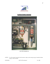
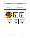
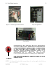
Figure 9-2 shows the inside of a typical turbine controller, Figure 9-3 the capacitor box and
Figure 9-4 the PLC.