


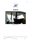


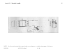
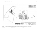
Appendix A-1 50 Hz Specifications Sheet
NOTICE: Use of the material contained in this document is subject to the warning on page Iv and the disclaimer on page v of this
document.
DOC012R02 AOC 15/50 User Manual Nov 2001
109
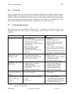
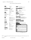
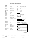
AOC 15/50 50 Hz WTG Design Specifications
SYSTEM
Type Grid Connected
Configuration Horizontal Axis
Rotor Diameter 15 m (49.2 ft)
Centerline Hub Height 25 m (82 ft)
PERFORMANCE PARAMETERS
Rated Electrical Power 50 kW @12.0 m/s (26.8 mph)
Wind Speed @hub height 25 m (82 ft)
cut-in 4.6 m/s (10.2 mph)
shut-down (high wind) 22.4 m/s ( 50 mph)
peak (survival) 59.5 m/s (133 mph)
Calculated Annual Output
@ 100 % availability 5.4 m/s (12 mph) 85,000 kWh
6.7 m/s (15 mph) 145,000 kWh
8.0 m/s (18 mph) 199,000 kWh
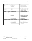
ROTOR
Type of Hub Fixed Pitch
Rotor Diameter 15 m (49.2 ft)
Swept Area 177 m ²(1902 ft²)
Number of Blades 3
Rotor Solidity 0.077
Rotor Speed @ rated wind speed 62 rpm
Location Relative to Tower Downwind
Cone Angle 6º
Tilt Angle 0º
Rotor Tip Speed 48.6 m/s (109 mph) @ 50 Hz
Design Tip Speed 6.1
BLADE
Length 7.2 m (23.7 ft)
Material Wood/epoxy laminate or Epoxy/glass fibre
Airfoil (type) NREL, Thick Series, modified
Twist 7° outer blade
Root Chord 457 mm (18 in) @ 4% 279 mm (11in)
Max Chord 749 mm (29.5 in) @ 39% 2925 mm (115 in)
Tip Chord 406 mm (16 in) @ 100 % 7500 mm (295 in)
Chord Taper Ratio ± 2:1
Overspeed Device Electro-magnetic tip brake
Hub Attachment Embedded female bolt receptors
Blade Weight 150 kg (330 lbs) approximate
GENERATOR
Type 3 phase/4 pole asynchronous
Rated Temperature -25°c
Frequency (Hz) 50 Hz
Voltage (V) 400, 3 phase @ 50 Hz (380V,415V also avail)
kW @ Rated Wind Speed 50 kW
kW @ Peak Continuous 55 kW
Speed RPM (nominal) 1500 @ 50 Hz
Winding Configuration Ungrounded WYE
Insulation Class F
Enclosure Totally Enclosed Air Over (TEAO)
Frame Size 365 TC
Mounting Direct mount to transmission
Options Arctic low temp. shafting (-40°c)
TRANSMISSION
Type Planetary
Housing Ductile iron-integrated casting
Ratio (rotor to gen. speed) 1 to 24.57 (50 Hz)
Rating, output horse power 88
Lubrication Synthetic gear oil/non toxic
Heater (option) Arctic version, electric
YAW SYSTEM
Normal Free, rotates 360 degrees
Optional Yaw damping-required when known conditions
frequently exceed 50° yaw rate per second.
DRIVE TRAIN TOWER INTERFACE
Structural Yaw bearing mounted on tower top casting
Electrical Twist Cable
TOWER
Type Galvanized 3 legged, bolted lattice , self-supporting
Tower Height 24.4 m (80 ft)
Options 30.5 m (100 ft),
Tilt down 24.4 m (80 ft)
FOUNDATION
Type Concrete or special
Anchor Bolts Certified ASTMA-A-193-Grade B7
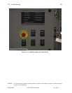
CONTROL SYSTEM
Type PLC based
Control Inputs Wind speed, generator shaft speed
Control Outputs Line interconnection, brake deployment
Communications Serial link to central computer for energy monitor
and maintenance dispatch (optional
Enclosures NEMA 1, NEMA 4 (optional)
Soft Start Optional
ROTOR SPEED CONTROL
Production Blade stall increases with increased wind velocity
Normal Start up Aerodynamic, electrical boost if necessary
Shut-down Control system simultaneously applies dynamic brake and
deploys tip brakes. Parking brake brings rotor to standstill.
Back-up Overspeed Control: Centrifugally activated tip brakes deploy
BRAKE SYSTEM CONTROL
Fail-safe brakes automatically deploy when grid failure occurs.
APPROXIMATE SYSTEM DESIGN WEIGHTS
Tower 3,210 kgs (7,080 lbs)
Rotor & Drivetrain 2,420 kgs ( 5,340 lbs)
Weight on Foundation 5,630 kgs (12,420 lbs)
DESIGN LIFE: 30 Years
DESIGN STANDARDS:
Applicable Standards, AWEA, EIA and IEC
DOCUMENTATION:
Installation Guide and Operation & Maintenance Manual
SCHEDULED MAINTENANCE: Semi-annual or after severe events.
NOTE 1:
Atlantic Orient Corporation and its affiliates are constantly working
to improve their products, therefore, product specifications are sub
ject to
change without notice.
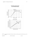
NOTE 2:
Power curves show typical power available at the controller based
on a combination of measured and calculated data. Annual energy is
calculated using power curves and a Rayleigh wind speed distribution.
Energy prod
uction may be greater or lesser dependent upon actual wind
resources and site conditions, and will vary with wind turbine maintenance,
altitude, temperature, topography and the proximity to other structures
including wind turbines.
NOTE 3: For design opt
ions to accommodate severe climates or unusual
circumstances please contact the corporate office in Norwich, Vermont USA
NOTE 4:
For integration into high penetration wind-
diesel systems and
village electrification schemes contact the corporate office in
Norwich, VT
USA for technical support and systems design.
REV. September 19
th
, 2000