


Axtreme Boom (Asy Man) 07/06
© 2006 Alamo Industrial
Section 8- 4
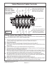
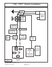
Mechanical
Remote Cable
Controled Valve
(Standard)
Figure 1
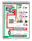
Door
(Yellow / White)
Tilt
(Red / White)
Tilt
(Red)
Dipper
(Blue / White)
Dipper
(Blue)
Lift
(Orange / White)
Lift
(Orange)
Swing
(Green / White)
Swing
(Green)
Pressure Supply (Port P1)
Return (Port T2)
Door
(Yellow)
1
2
3
4
1
2
2
A
B
AA
A
A
BB
BB
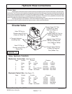
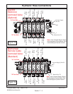
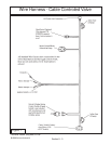
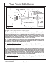
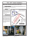
Valve Remote Cable Controls
Hoses have colored plastic ties
on them that match the colors
listed here, this is a guide to
which hose connects where
Hoses have colored plastic ties
on them that match the colors
listed here, this is a guide to
which hose connects where
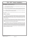
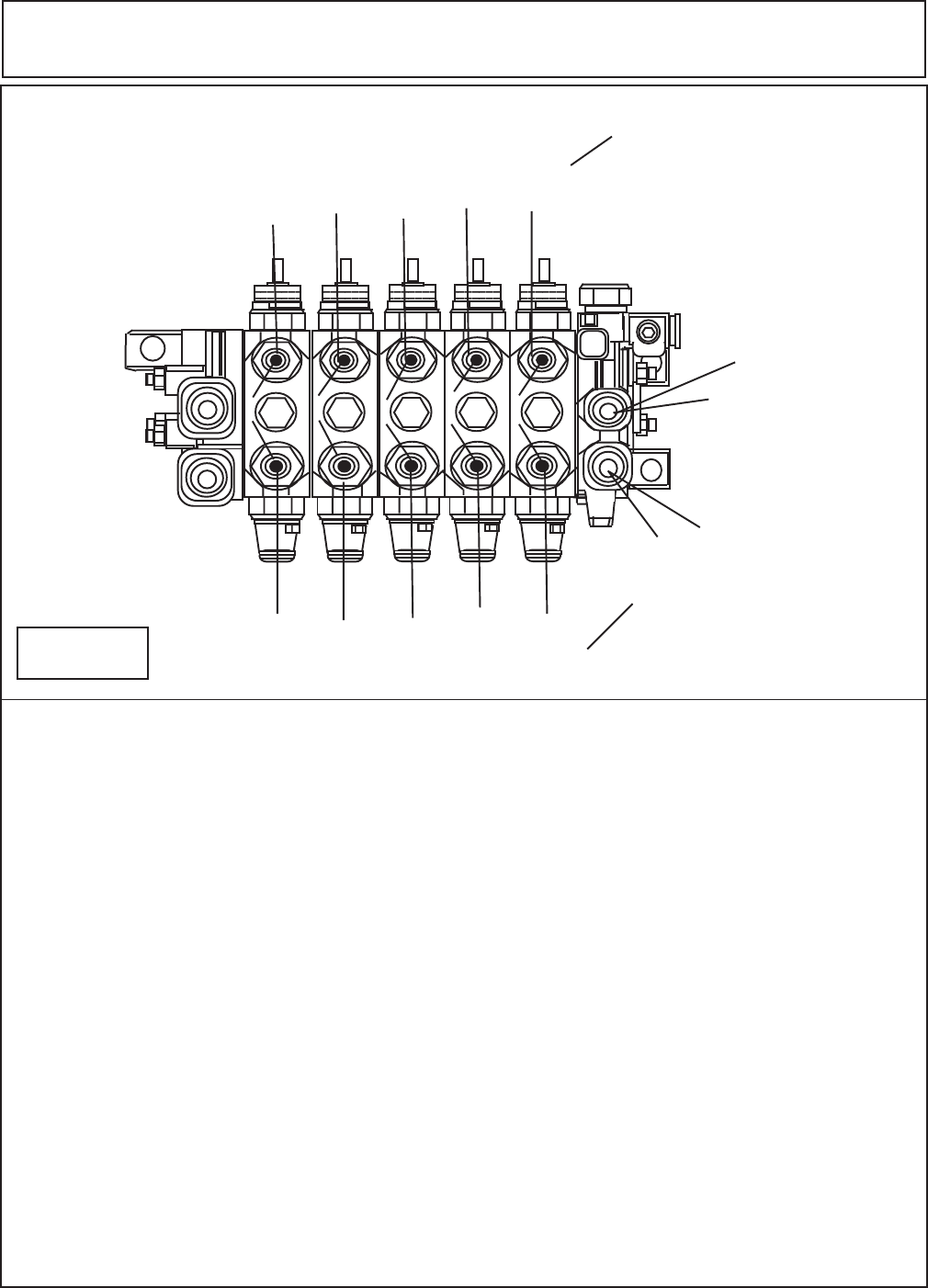
Cylinder Control Valve Cables To Valve Spools:
The Remote Control Cables Connection to the valve and the Control Handle assembly. See
Figure 2 for listing of items (1 thru 8 ) listed in assembly steps.
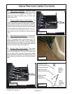
1 Remove the phillps head screws that are in the valve body next to the spool end (8). There are bolts
in kit that will be used to replace these screws when needed (See Figure 2).
2. Slide the Bolt flange (8)
3. Thread .750-16 NF jam nut entire length of threaded hub and onto the cable (7).
4. Place flange on sleeve and thread flange / sleeve assembly entire length of threaded hub and onto
cable (2 & 6).
5. Thread .250-28 NF jam nut onto cable threaded rod until it bottoms (3).
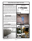
6. Place connector onto threaded rod and against jam nut. Align connector so it will mate with spool
terminal and secure jam nut against connector (4).
7. Slide the connector onto spool and align the holes. Insert pin through connector and spool holes (5).
The control cables will need to inserted through the floor of the tractor cab and the Control Levers
will need to be assembled to the cables before continuing with the next assembly steps.
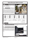
8. With cable attached to the valve and control levers, turn the flange / sleeve assembly onto the
threaded hub until it is flush with the valve face. When turning the flange / sleeve assembly make
certain that the control levers remains in the neutral position.
9. Tighten the .750-16 NF jam nut against the sleeve to lock in position (6).
10. Bring flange into position and bolt assembly to valve housing. Tighten screws sufficiently to flatten
lockwashers / secure flange (8). Caution, overtightening flange bolts will distort flange.