


© 2006 Alamo Group Inc.
Section 7 - 6
Axtreme Boom (Asy. Man) 07/06
Boom / Head Installation
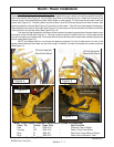
Figure 11
Figure 12
Figure 13
Sleeving Material for
Hoses
Hose Support Bracket
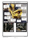
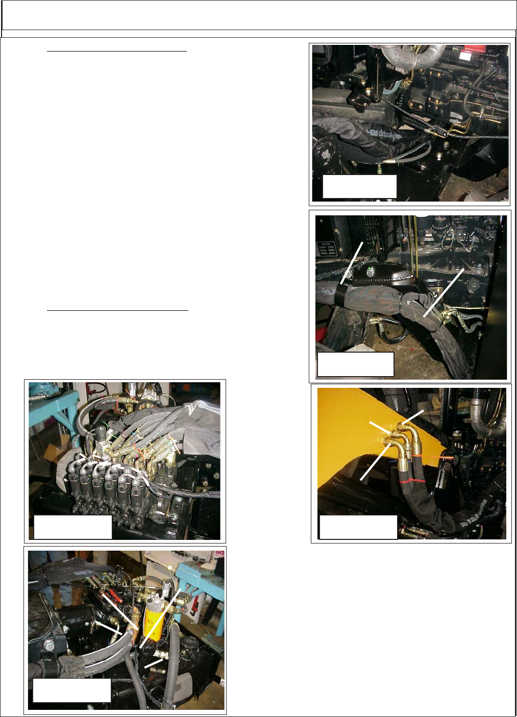
Figure 14
Red Tie
Blue Tie
Orange Tie
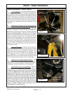
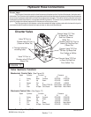
12. Routing Boom Hoses to Pump Boom hose to pump will
be routed on RH Side of tractor, They are run through sleeving
material and hose support bracket (See Figure 15). The Pump
hoses must be connected correctly to boom and pump. There
are 2 Pump to motor hoses and 1 motor case drain return hose
for a total of 3. (Note Motor Case Drain hose will be run through
the Oil Cooler and then return to tank).
First is the hose with the red plastic tie the lower
connection at Boom, (See Figure 14), this is the pressure
supply from pump, lower connection at pump (See Figure 14) to
the motor connection at the boom.
Second is hose with orange plastic tie, upper connec-
tion at boom (See Figure 14). This is the Return hose from the
motor upper connection at pump (See Figure 14).
Third is Hose with blue plastic tie, middle connection at
boom (See Figure 14) which is case drain from motor. Hose
connects to the Oil Cooler / Fan Asy mounted under tractor
bolster behind hyd tank. There is short hose which will not have
plastic tie that will connect to oil cooler, then goes to tank return
(See Figure 16).
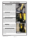
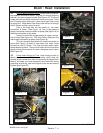
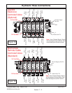
13. Pump Hose Routing at Tank. Hose routing at tank is
shown as reference to Pump hose routing which most will
already be connected when tank and pump asy is shipped from
factory. All hoses you must disconnect and reconnect during
pump and/ or tank asy, refer to this figure for the correct location
of hose (See Figure 15).
Figure 16
Red Tie
(Bottom Fitting)
Orange Tie
(Top Fitting)
No Tie (F/ Oil Cooler
to Tank)
Hose Support
Bracket
Rev 02-20-07