


© 2006 Alamo Group Inc.
Section 7 - 2
Axtreme Boom (Asy. Man) 07/06
Boom / Head Installation
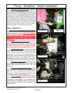
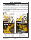
Figure 1
Swing Cyl. Hose
with Green /
White Tie
Swing Cyl. Hose
with Green Tie
Rear of Tractor
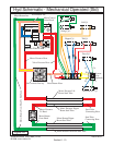
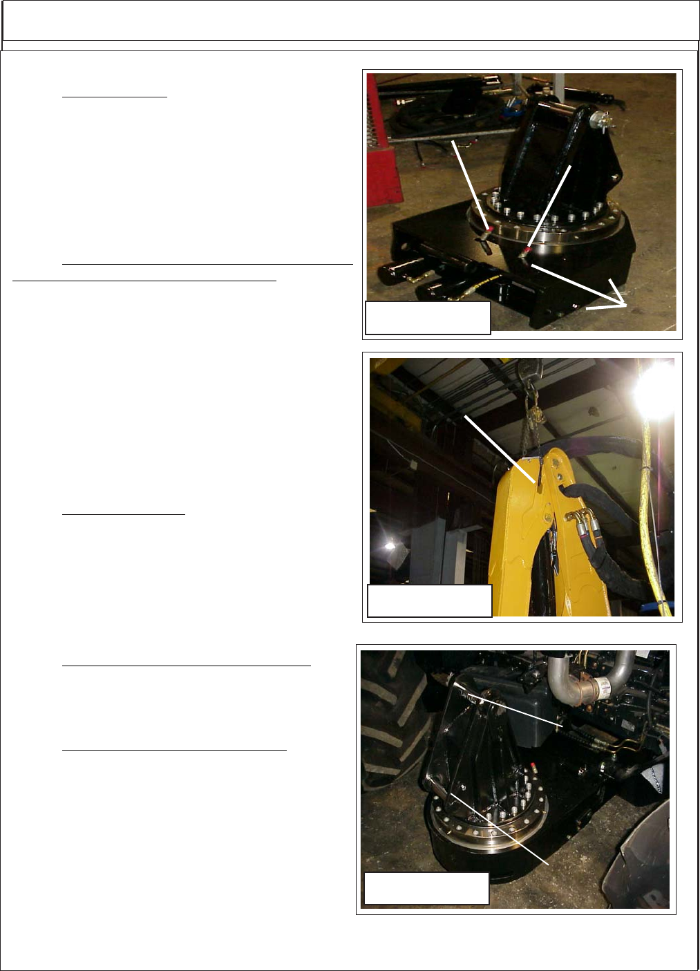
Boom Installation / Boom Hoses:
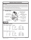
1. Turret Assembly, The turret assembly has the
cylinders connected and the hoses are connected to
the cylinders. The end of the hoses will be sticking up
through the turret mount weldment between turret and
tractor. The hoses will need to be connected there and
routed to the hydraulic control valve. One hose will
have a Green Tie and one a green and white tie where
the come up throught the turret mount weldment. (See
Figure 3).
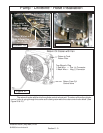
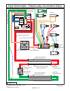
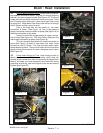
2. Booms Are recieved from the factory with the
Sections of Boom Assmebled to together. The Boom
Sections are assembled with the hydraulic lines and
cylinder connected. The hose will be connected to the
boom that are routed to the control valve and diverter
valve and bundled together. (See Figure 4). The Boom
Hoses are protruding out the turret mount end of the
boom. The Hose connections on the head end will be
shipped with metal caps on them, these are to protect
the lines from contamination and should not be re-
moved until the hoses are being installed (See Figure
4). The hose that attaches to the boom are sent in-
stalled on the head assembly and the hose will also
have plugs in them.
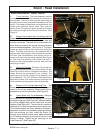
3. Boom Lift Cylinder. The boom lift cylinder will
be connected to the boom at the rod end of the cylinder
(See Figure 2 & 4) when it is shipped from factory. The
hoses will also be connected to the cylinder. The
retaining pin for the lift cylinder will be located in the
turret assembly. The Lift Cylinder will be fastened to
boom with tie wire. It will not be required to remove this
tie wire before mounting boom on turret assembly. -
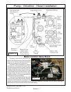
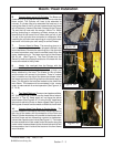
4. Booms & Lift Cylinder Mounting Pins. The
Boom and lift cylinder mounting pins are shipped in-
stalled in the turrert assembly. Remove both pins in
preparation to mounting the boom. (See Figure 3)
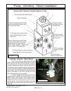
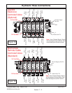
5. Lower Boom onto Turret Assembly. Using an
over head hoist lift the boom by placing a lift strap at
the boom hinge point (See Figure 2), the boom assem-
bly will be shipped with the two boom end tie wired
together (See Figure 3A). The wire tie will need to be
removed as it is tied through the boom hinge pin hole.
Lift the boom above the turret assembly and lower it
back down onto the turret assembly aligning the boom
with the mounting pin hole. Install the Mount Pin
through the turret and into the boom. Make certain the
pin is installed correctly as one side of the pin is self
locking in design. Tighten the pin retaining nut and
install cotter pin. (See Figure 3C)
Figure 3
Main Boom
Mount Pin
Lift Cyl. Base
End Mount Pin
Figure 2
Lifting
Point