


© 2006 Alamo Group Inc.
Section 7 - 4
Axtreme Boom (Asy. Man) 07/06
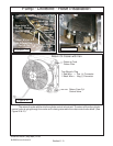
Figure 4
Figure 5
Figure 6
Figure 7
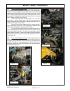
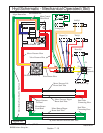
50 Inch Head w/o
Swivel Hitch Mount
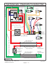
50 Inch Head w/o
Swivel Hitch Mount
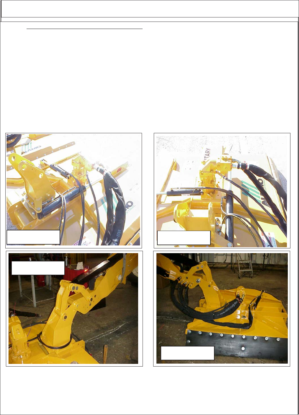
60 Inch Head with
Swivel Hitch Mount
60 Inch Head with
Swivel Hitch Mount
Boom / Head Installation
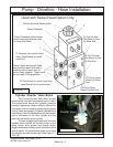
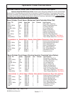
Motor Circuit Hoses to Boom Connections: (Listed as reference)
Color Tie (Code) Hose Size Hyd. Function
Red R SAE # 16 -- Pressure Flow to Motor
Orange OR SAE # 16 -- Return Flow From Motor
Blue B SAE # 8 -- Case Flow From Motor to Boom
Blue B SAE # 12 -- Case Flow at Boom to Tank
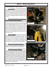
11. Routing Cylinder Hoses from Boom to Valve The Hose from the boom to the valve will be split, the four
hoses to the door cylinder and swivel cylinder will run together through a section of sleeving material to the RH
side of the tractor (See Figure 9). On the Right hand side of the tractor the four hoses will connect to the
diverter valve in the coded locations (See Hose Codes on next pages). Tie the hoses to the frame under the
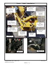
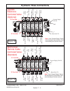
tractor (See Figure 10). The two hoses from the diverter valve will continue along the LH side of tractor with
sleeving material over them (See Figure 10) to the front of the tractor. They will have hose support brackets on
them that bolt to the side of the tractor (See Figure 10) where they will be connected to the valve at the Door
/ Swivel Ports in the correct order (See Figure 13 & 14).
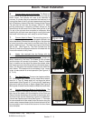
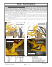
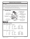
The other cylinder hoses from the boom will be inserted into sleeving material and also be routed under
the tractor to the LH side (See Figure 11). They will continue up the LH side to the front of the tractor where
they will connect to the valves ports. The hoses will be held to the frame with metal hose holders bolted to the
tractor frame (See Figure 12).
NOTE: the hoses must be run through the sleeving material. On the LH side there is a hole in the
center frame weldment the hoses can be run through it if wanted. Connect the hoses to the valve as shown
(See Figure 11)
Rev 02-20-07