


Axtreme Boom (Asy Man) 07/06
© 2006 Alamo Industrial
Section 6 - 2
Pump - Driveline - Hose Removal
Pump - Driveline - Hose Information:
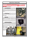
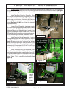
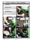
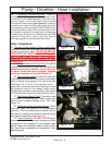
This Section covers the Pump and Driveline Components. Some precautions must be followed during the
assembly Process before unit is ever started for the first time. (See Hyd Schematic in this section for hyd routing).
A. Tractor must be disabled to prevent accidental engine start and prevent damge to components.
B. All Fittings, Hose, Cylinders, Tank must be kept plugged at all times, No part of the Hydraulic System can
be left open at any time
C. All Tools, Work Area, Components and Workers Hands must remain Clean when working on any part of
the Hydraulic System.
D. All components should be rechecked for tightness at least twice, Hose routing also double checked.
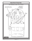
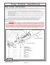
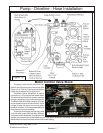
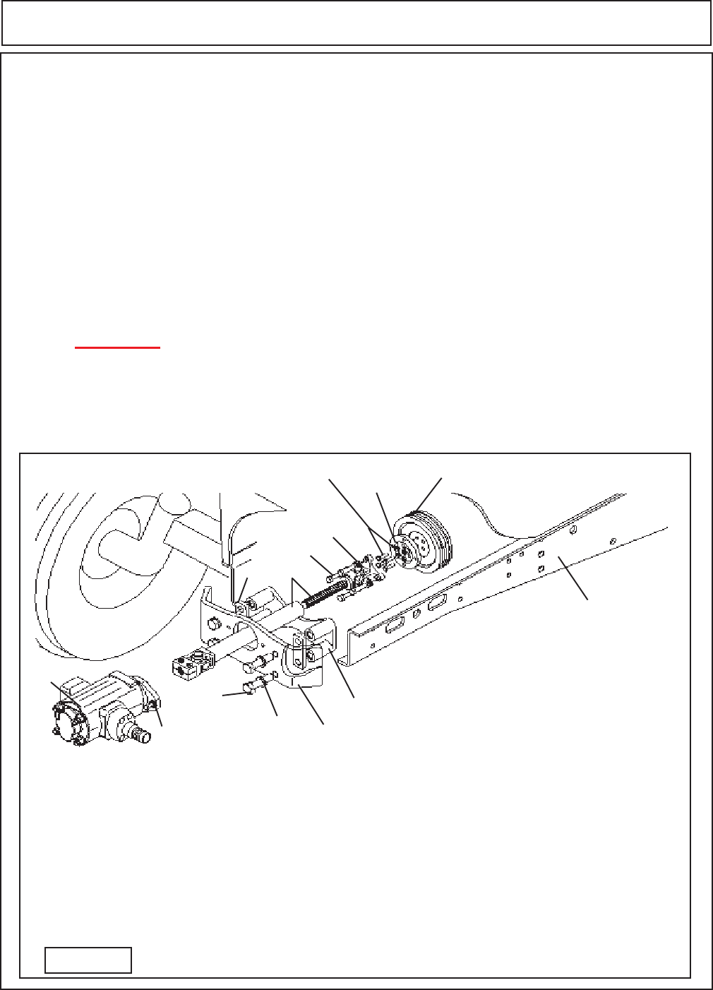
Componets shown here are a general illustration of the pump driveshaft configuration. The actual
configuration used on a specific tractor may vary. See the assembly drawings shipped with the unit
when shipped from the factory. Keep these drawings with the assembly, parts, service, operators
manuals for future reference.
1
7
8,9
Tractor Front Casting
2
3
4
5
6
Tractor Frame Rails
Tractor Crankshaft Pulley
Existing Tractor Bolts & Washers
Pump
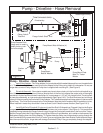
Item Part No. Qty Description
1 ------------- 1 Front Pump Plate
2 ------------- 1 Pulley Adapter
3 ------------- 1 Driveline Assembly
4 ------------- 4 Bolt
5 ------------- 4 Lockwasher
6 ------------- 4 Bolt
7 ------------- 4 Lockwasher
8 ------------- 2 Bolt
9 ------------- 2 Lockwasher
Figure 1
CAUTION: Shown in Figure 1 is a basic pump driveline configuration, BUT NOT
the only configuration. Components will vary with the type tractor that the Axtreme
Boom is mounted on. See the Assembly Drawings and/or Parts manual that is for the
unit mounted to your tractor. Some models may reguire modifications to the tractor
that are not listed in this manual, see the assembly drawing shipped with the unit.