


© 2006 Alamo Group Inc.
Section 7 - 3
Axtreme Boom (Asy. Man) 07/06
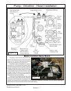
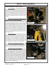
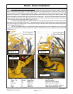
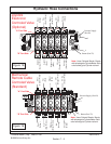
6. Connect lower end of Lift Cylinder. The Base end
(lower end) of lift cylinder will mount into the turret under the
boom mount. The Cylinder will have to be extended to
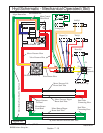
connect, If cylinder has to be extended the best way is to
unplug the ends of the lift cylinder hoses where they come
out of the boom, these will be the # 6 hose with the Orange
Tie and the # 6 hose with the orange / White Tie. When
pulling (extending or collapsing cylinder) always put the
opened end of the hoses into a clean drain pan as oil will
run out of the cylinder when extended or collapsed. After
installing the cylinder lower mounting pin re-plug the hoses
that were in the drain pan until ready to connect hoses.
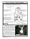
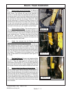
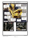
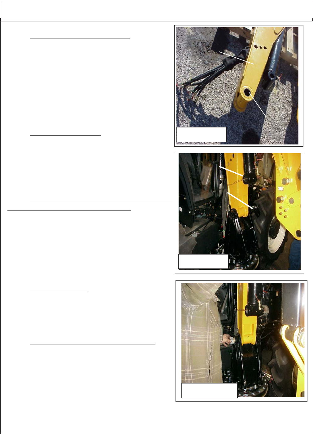
7. Connect Head to Boom. The mounting pins to in-
stall the head onto the boom will be shipped installed in the
mount weldment. Remove the mounting pins. Use the hoist
to lower boom down over head to connect head, Align the
upper head mount pin. The lower mount pin is the connect
the lift link. (See Figure 4). The Door Cylinder and the
Swivel Cylinder are shipped installed on the head with the
hoses connected to the cylinder.
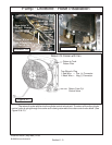
8. Heads Are received from the Factory with the
Cylinder and Head hoses Attached to Head. The head will
be received with the door cylinder, swivel cylinder and
Motor attached to the head. The Hoses for the cylinders
and the motor will connect to the boom. There is a decal
that is installed on the side of the boom that shows where
the hoses connect to the fitting that have the metal caps on
them. The fittings for the head are located on the side of the
main Boom. The hoses must be connected in the correct
order to make certain of correct operation (See Figure 4, 5,
6, 7 & 8).
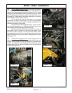
9. Two Head Options. There are two heads available,
60" (See Figure 4 & 5) which has the head Swivel attach-
ment on it. The 50" Head which will not have the swivel
attachement (See Figure 6 & 7) If using the 50" head leave
the ports for swivel cylinder on boom capped (See Figure 8)
More types of heads are tobe made available at a later date.
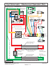
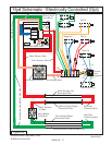
10. Connect Hose From Boom to Control Valve. The
cylinder hoses will connect to the control valve mounted on
the front of the tractor with the exception of the Door and
Swivel Cylinder hoses they will connect to the diverter valve
and then there are two hoses that connect to thediverterr
valve to the 6 spool control valve (See Figure 11). The hoses
for door and swivel will be routed under the tractor along the
center under frame weldment to the diverted valve which will
be mounted on the LH side of the tractor on the front frame
mount bracket.
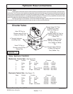
Boom / Head Installation
Figure 3A
Turret End
Of Boom
Boom Mounting
Pin Hole
Figure 3B
Mount Pin
Lift Cylinder
Figure 3C