


Starting the Commissioning Test File
152607 3–3
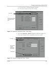
Serial Number
1. Enter the information required by GUI in the white text boxes on the form that
appears next. The converter serial number is located on a label placed on the
lower-left front of the Main Inverter Enclosure door.
2. Once you finish recording the required information, click on the check box to
indicate the task is complete. Go to the next step by clicking on the "N
EXT"
button.
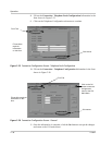
Verify AC Voltage
1. Open the door of the AC Interface Enclosure and verify that the Grid AC
cables have been installed at S1-2T1, S1-4T2, S1-6T3, TB11, and TB12.
2. With a voltmeter, verify if AC Grid voltage is present at the bottom of S1-
2T1, S1-4T2, S1-6T3. These fuses are located in the AC Interface Enclosure.
a) If voltage is correct, verify phasing using a phase rotation meter. The
phase rotation should be clockwise “A, B, C”.
b) If the voltage is not present, contact the installer, site electrician or site
operator to supply grid voltage to the unit.
3. If grid voltage is not available to the unit, open the AC Disconnect Switch
(S1) and lock the AC Interface Enclosure. The Commissioning Test procedure
must cease at this point. Do not attempt to continue the test until each step can
be checked and verified.
a) If grid voltage is not available and the Commissioning Test must be
stopped, SAVE the Commissioning File. This file will be used once grid
voltage has been applied and verified.
4. Once you finish verifying AC voltages, go back to the GUI Commissioning
Procedure and click on the check box to indicate the task is complete. Go to
the next step by clicking on the "N
EXT" button.
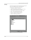
Verify DC Voltage
1. Open up the DC Interface Enclosure and verify that the PV DC cables have
been installed correctly.
2. With a voltmeter, verify if PV DC voltage is present at S2-6 and K2-6T3.
3. Verify the correct polarity.
4. If the voltage is not present, contact the installer, site electrician or site
operator to supply PV voltage to the unit.
5. If PV DC voltage is not available to the unit, open the DC Disconnect Switch
(S2) and lock the DC Interface Enclosure. The Commissioning Test procedure
must cease at this point. Do not attempt to continue the test until each step can
be checked and verified.
a) If PV voltage is not available and the Commissioning Test must be
stopped, SAVE the Commissioning File. This file will be used once PV
DC voltage has been applied and verified.