


Specifications
A–4 152607
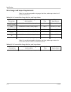
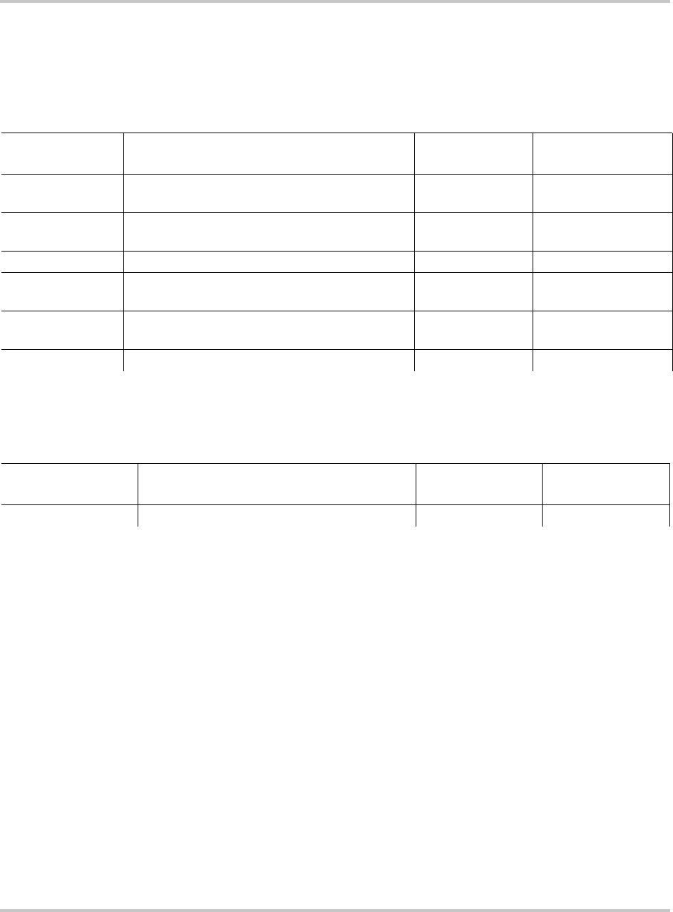
Wire Gauge and Torque Requirements
Table A-4 provides acceptable wire gauges, bolt sizes, and torque values for AC
terminal connections.
Table A-5 provides acceptable wire gauges, bolt sizes, and torque values to be
connected to the PV225S DC terminal connections.
Table A-4
AC Terminal Wire Gauge, Bolt Size, and Torque Values
AC Terminal
Connections
Acceptable Wire Size Range
(both models)
Bolt (Hardware)
Size
Torqu e
Requirements
TB1
(Chassis Ground)
500 MCM to #4 AWG (1 stud per pole) 3/8-16 420 in-lb (47.5 Nm)
TB12
(System Ground)
500 MCM to #4 AWG (1 stud per pole) 3/8-16 420 in-lb (47.5 Nm)
TB11 (Neutral) 500 MCM to #4 AWG (1 stud per pole) 3/8-16 228 in-lb (25.7 Nm)
S1-2T1, S1-4T2,
S1-6T3
350 MCM to #6 AWG (1 stud per phase) M10 310 in-lb (35.0 Nm)
T6-X1, T6-X2, T6-
X3
350 MCM to #6 AWG (2 stud per phase) 3/8-16 420 in-lb (47.45 Nm)
TB5, TB6, TB7 350 MCM to #4 AWG (6 openings per phase) 3/8 Hex 375 in-lb (42.4 Nm)
Table A-5
DC Terminal Wire Gauge, Bolt Size, and Torque Values
DC Terminal
Connections
Acceptable Wire Size Range
(both models)
Bolt (Hardware)
Size
Torque
Requirements
S2-6, K2-6T3, TB4 600 MCM to #4 AWG (2 openings per pole) 1/2 Hex 600 in-lb (67.8 Nm)