


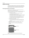
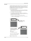

Operator Interface
152607 2–11
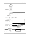
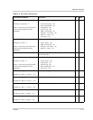
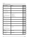
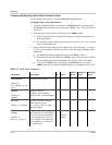
Table 2-2
R
EAD
Menu Descriptions
Operational Parameter Description ID Units
Current Operating State
Displays as:
System: *
where * can be any one of the states
listed in the description for this
parameter.
Current system states include the following.
Initializing (0)
Key-disabled (1)
Shutdown (2)
Starting (3)
PWR Tracking (4)
Manual Current (5)
Matrix Test (6)
Faulted (7)
1N/A
System Goal State
Displays as:
Goal: *
where * can be any one of the states
listed in the description for this
parameter.
Goal States include the following.
Shut Down (0)
PWR Tracking (1)
Manual Current (2)
Matrix Test (3)
2N/A
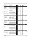
Fault code See “Fault Code Descriptions” on page 4–4 for a detailed
list of Fault Codes.
3N/A
Inverter State
Displays as:
INV: *
where * can be any one of the states
listed in the description for this
parameter.
Inverter States includes the following.
Shut Down (0)
Stand-by (1)
Starting (2)
Main-Setting (3)
On-Line (4)
4N/A
Line A–B voltage
Displays as:
INV A volts: xxx
Line to line voltage 5 V
rms
Line B–C voltage
Displays as:
INV B volts: xxx
Line to line voltage 6 V
rms
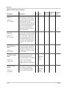
Line C–A voltage
Displays as:
INV C volts: xxx
Line to line voltage 7 V
rms
Phase A current
Displays as:
INV A amps: xxx
Phase A current 8 A
rms
Phase B current
Displays as:
INV B amps: xxx
Phase B current 9 A
rms