


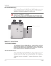

Operation Features
152607 1–3
Peak Power Tracking
An advanced, field-proven, Maximum Peak Power Tracker (MPPT) algorithm
integrated within the PV225S control software ensures the optimum power
throughput for harvesting energy from the photovoltaic array. The peak power
voltage point of a PV array can vary, primarily depending upon solar irradiance
and surface temperature of the PV panels. This peak power voltage point is
somewhat volatile, and can easily move along the I-V curve of the PV array every
few seconds. The MPPT algorithm allows the PV225S to constantly seek the
optimum voltage and current operating points of the PV array, and maintain the
maximum peak PV output power.
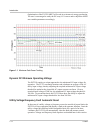
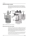
Accessible via the UFCU, there are five user settable parameters that control the
behavior of the maximum peak power tracker within the PV225S. As show in
Figure 1-1 on page 1–4, user settable parameters include:
• PPT V Ref (ID# 37),
• I PPT Max (ID#42),
• PPT Enable (ID# 44),
• PPT Rate (ID# 45), and
• PPT V Step (ID# 46).
Upon entering the Power Tracking mode, it takes approximately 20 seconds for
the PV225S to ramp the PV voltage to the “PPT V Ref” setpoint regardless of the
actual PV voltage.
With the “PPT Enable” set to “0” (power tracker disabled), the PV225S will
regulate the DC Bus at the “PPT V Ref” setpoint. Regulating the DC bus means
drawing more or less current out of the PV array to maintain this desired voltage.
With the “PPT Enable” set to “1” (power tracker enabled), followed by the
expiration of the “PPT Rate” (MPPT decision frequency), the MPPT will reduce
the reference voltage by an amount equal to the “PPT V Step” value.
At this point the MPPT will compare the amount of AC output power produced to
the previous amount of AC power produced by the PV225S. If the output power
has increased, the next change made (after “PPT Rate” has again expired) to the
reference voltage, will be in the same direction.
Conversely, if the power comparison proves undesirable, the power tracker will
reverse the direction of the change to the “PPT_V Step”. The MPPT algorithm
within the PV225S will then continue this ongoing process of “stepping and
comparing” in order to seek the maximum power throughput from the PV array.
The changes made by the MPPT to the reference voltage are restricted to ± 20% of
“PPT V Ref” and by the maximum and minimum PV input voltage (600 and
300 volts respectively). Also, the MPPT will not attempt to produce power greater
than that allowed by the “I PPT Max” setpoint. If available PV power is above the
maximum allowable power level of the PV225S, the MPPT will increase voltage
as needed to maintain output power below rated maximum.