


Operation
2–6 152607
Operator Interface
The purpose of the operator interface is to provide a means of communicating
critical operational information to and from the unit. This communication occurs
between the operator and the UFCU Keypad and LCD display or between the
operator and a personal computer running the Xantrex Solar GUI software.
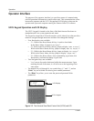
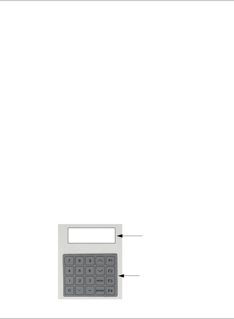
UFCU Keypad Operation and LCD Display
The UFCU keypad is located on the front of the Main Inverter Enclosure to
manipulate and view system operation and status.
The keypad is comprised of 20 touch-sensitive, peizio electric keys that provide a
means to navigate through the menus and alter user-changeable settings.
• Four function keys are available.
• F1 - While in the R
EAD Menu, this key is used to clear faults.
In the W
RITE Menu, it jumps to set “
Goal
:”.
• F2 - While in the R
EAD Menu, this key jumps to display “
INV A Volts
”.
While in the W
RITE Menu, this key jumps to display “
Max AC Volts %
”.
• F3 - While in the R
EAD Menu, this key jumps to display “
PV Volts:
”.
While in the W
RITE Menu, this key jumps to display “
Input #0:
”.
• F4 - While in the W
RITE Menu, when commanding a goal state, this
function key confirms the change in goal state.
• Two Navigation keys are available.
• \/ or /\ moves forward or backward within the menu structure. Upon
reaching the end of the menu, it will roll-over to the beginning of the
same menu.
• Ten numeric keys (0 through 9), two symbol keys (“.” and “-”), and an
“E
NTER” key are available for entering user-settable parameters.
• The “M
ENU” key allows you to enter the password-protected Write
parameters.
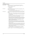
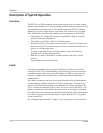
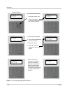
Figure 2-2
The Universal Front Panel Control Unit (UFCU) and LCD
LCD Display
UFCU Keypad
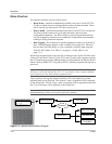
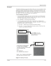
System: PWR Tracking
Inv: Online
Pv: Online
Goal : PWR Tracking
Standard Display